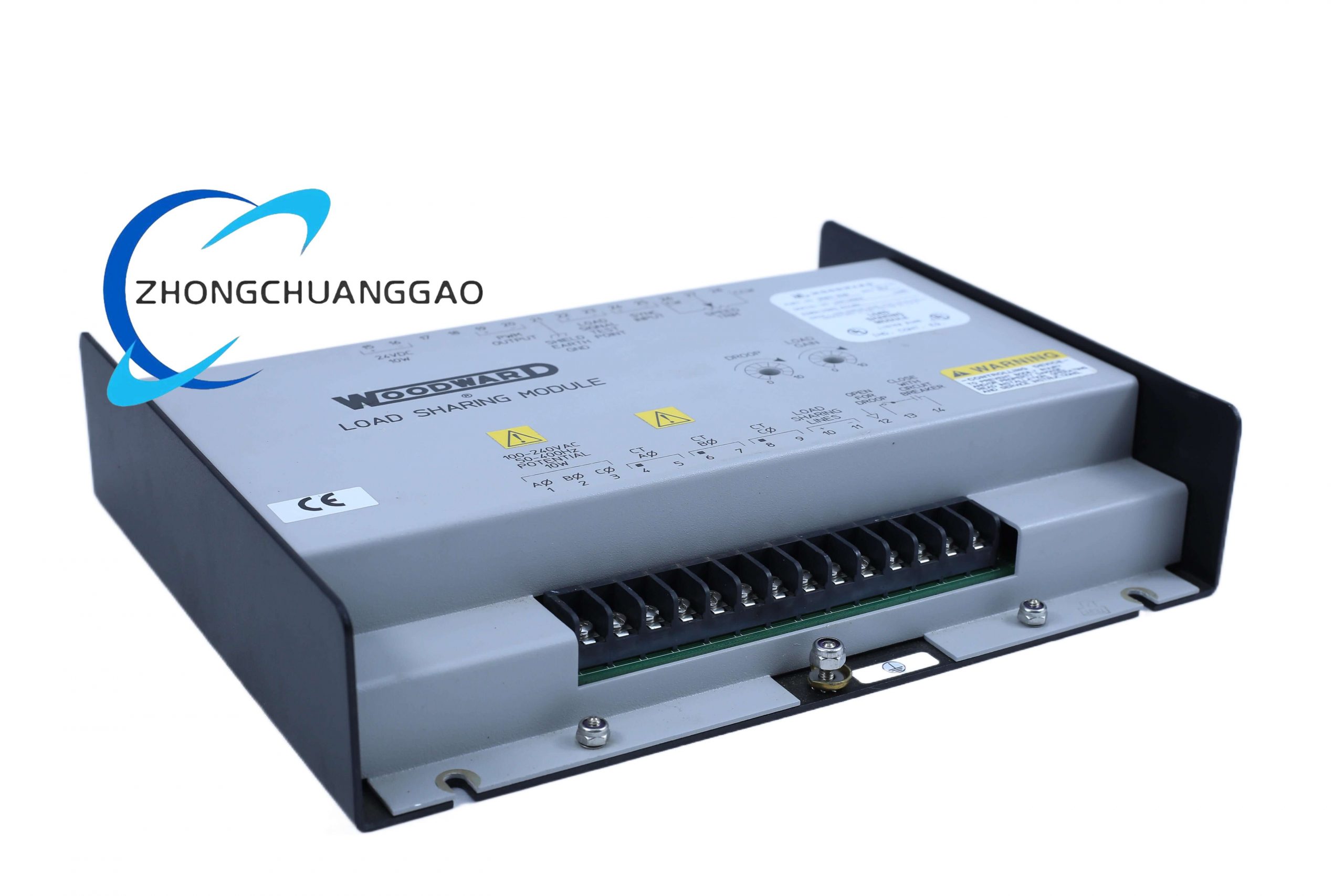
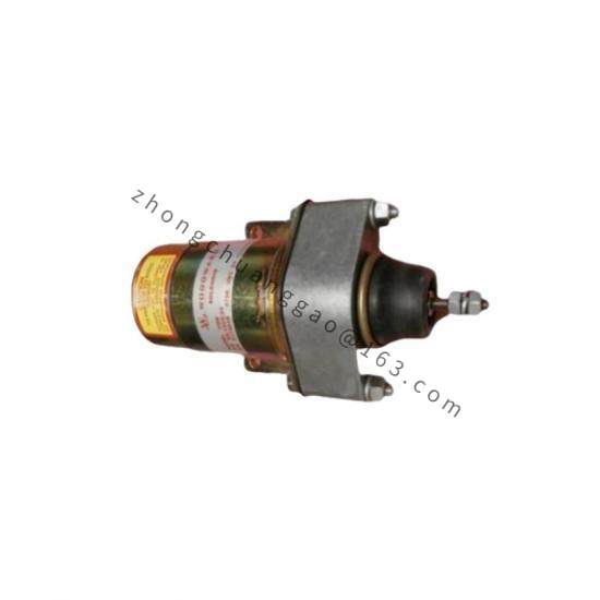
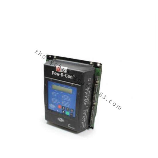
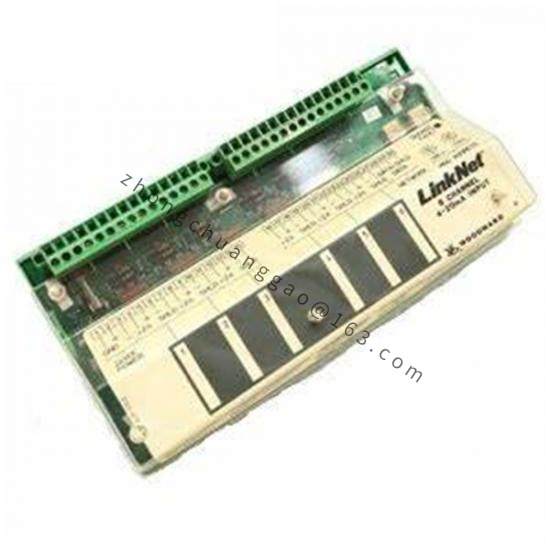
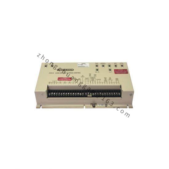
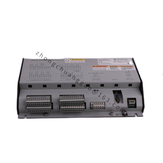
Product Introduction: A member of the Woodward 2301A series 9905/9907 product line. This series of controllers is used to control the load sharing and speed of generators driven by diesel engines, gasoline engines, steam turbines, or gas turbines.
Power Supply: Low-voltage models use 20–40 VDC external power supply; high-voltage models use 90–150 VDC or 88–132 VAC (45–440 Hz) external power supply
Speed Sensing: Switch-selectable speed ranges — 500 to 1500 Hz, 1000 to 3000 Hz, 2000 to 6000 Hz, 4000 to 12,000 Hz
Drive Output: Proportional actuator for positioning the fuel metering device
Load Measurement: Current and potential transformers for measuring generator load
Control Modes: Isochronous or Droop mode selectable; forward-acting or reverse-acting versions available; single or tandem actuator configurations supported
Functional Features:
Simultaneously implements speed control and load sharing
Speed control maintains prime mover (engine/turbine) speed stability
Load sharing ensures proportional load distribution among multiple parallel units, preventing single-unit overload or uneven load
Optional deceleration ramp: transition from rated speed to idle takes approximately 20 seconds
In reverse-acting systems, complete loss of actuator voltage drives the actuator to full fuel, allowing a backup mechanical governor to take control
Application Scenarios: Load sharing and speed control for diesel generators, gasoline generators, steam turbine power generation, and gas turbine power generation.
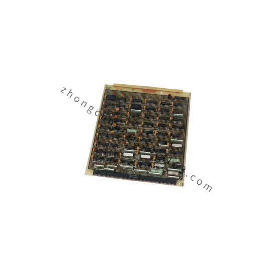
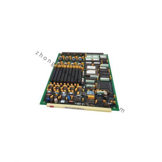
Material Composition: Sheet metal chassis, printed circuit board. All potentiometers are accessible from the front of the chassis.
Structural Features: Installed in a sheet metal chassis, consisting of a single printed circuit board.
Working Principle: By monitoring the output power of each generator and the prime mover speed signal, the electronic controller automatically adjusts the fuel supply of each unit, achieving load balancing during parallel operation. The relationship between prime mover speed and sensor output frequency is expressed as: Sensor Frequency (Hz) = (Number of teeth on speed sensing gear × Rated prime mover speed in RPM) / 60.
Installation Requirements:
Install in a “closed electrical operating area” or sealed industrial control cabinet
Select an installation location with adequate ventilation and heat dissipation space, maintenance space, avoiding direct water exposure or condensation-prone environments
Protect against influence from high-voltage/high-current equipment or EMI-generating equipment; avoid vibration; the controller must not be installed on the engine
Ambient temperature range: -40°C to +70°C
Speed signal lines and load sharing bus must use shielded twisted-pair cable with the shield grounded at a single point
Usage Precautions:
This controller does not include independent overspeed protection; the system must be equipped with an independent hardware overspeed shutdown device
For reverse-acting models, confirm that the actuator is a reverse-acting type; mismatch may cause runaway risk
Strictly distinguish power polarity during wiring; reverse connection will cause hardware damage
Anti-static protection must be observed when assembling/disassembling circuit boards