
Digital guide

You are here:

Woodward 9907-260

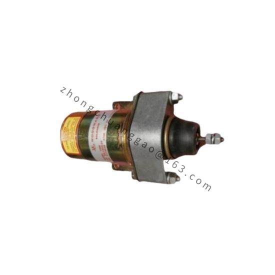
Product Introduction:​ The 9907-260 is an LO25 series electrically driven liquid fuel metering valve developed for liquid fuel control systems on industrial and aero-derivative gas turbines. It integrates a brushless DC motor, a rotary plate metering valve, and a non-contact position sensor into a single compact body, achieving precise closed-loop position control via a matched electronic driver. The LO25 series features self-cleaning shear-type metering, a high turn-down ratio, accurate flow control, and excellent corrosion resistance, forming the core executive element of gas turbine liquid fuel electronic control systems.
Detailed content

Technical Specifications:
  • Product Type: Electrically driven liquid fuel metering valve
  • Control Mode: Digital servo closed-loop control (with matched LQ/LO driver)
  • Output Form: Rotary plate angular position
  • Input Command Signal: 4 to 20 mA
  • Position Feedback Output: 4 to 20 mA
  • Driver Supply: 18 to 32 VDC
  • Operating Media: Diesel, JP series fuels, kerosene, gasoline, naphtha, gas turbine fuel oil, and other compliant distillates
  • Duty: Continuous modulation
Functional Features:
  • Fully integrated all-electric design with brushless DC motor, metering valve, and position sensor integrated in one body — no gear backlash
  • Self-cleaning shear-type metering via rotary plate, strong anti-pollution capability
  • High flow turn-down ratio exceeding 100:1
  • Flow accuracy of ±5% of nominal flow point or ±0.5% of maximum rated flow (whichever is greater)
  • Non-contact position sensing using a single- or three-speed resolver — no mechanical wear
  • Built-in differential pressure regulator: single-stage spring-loaded piston diaphragm type
  • Corrosion-resistant materials in all fuel-wetted parts
Application Scenarios:​ Liquid fuel metering for industrial gas turbines; fuel control for aero-derivative gas turbines; fuel regulation systems for power-generation gas turbines; fuel control for mechanical-drive gas turbines; marine gas turbine liquid fuel systems; fuel metering for combined heat and power (CHP) units.
Performance Parameters:
  • Flow Range: 80 to 26,000 lb/h (36 to 11,794 kg/h)
  • Maximum Fuel Inlet Pressure: 1,200 psig (8,274 kPa)
  • Maximum Fuel Bypass Pressure: 100 psig (690 kPa)
  • Regulated Differential Pressure: 50 psid (345 kPa) nominal
  • Pressurizing Valve Opening Pressure: 200 psid (1,379 kPa)
  • Full-Stroke Slew Rate: less than 0.100 s
  • Valve Shut-off Slew Rate: less than 50 ms
  • Motor Speed: 35 rad/s (typ.)
  • Metering Leakage: less than 80 lb/h @ 600 psig
  • Operating Temperature: -28°C to +103°C
  • Storage Temperature: -40°C to +103°C
  • Protection Rating: IP66
Material Composition:
  • Valve Body: High-strength aluminum alloy (standard) or stainless steel (marine environment)
  • Metering Plate: Corrosion-resistant hardened stainless steel, precision EDM-machined
  • Metering Sleeve: Integrated with motor rotor, corrosion-resistant material
  • Motor Housing: Aluminum alloy with cooling fins
  • Motor Rotor: Rare-earth permanent magnet material
  • Position Sensor: Single- or three-speed resolver
  • Differential Pressure Regulator: Spring-loaded piston diaphragm type
  • Seals: Fluoroelastomer (FKM)
  • Internal Fasteners: Stainless steel
Structural Features:
  • Integrated brushless DC motor co-axial with the metering valve — no gear transmission, eliminating backlash and wear
  • Rotary plate metering structure — metering sleeve integrated with motor rotor, single moving part for fuel metering
  • Hollow-shaft non-contact resolver directly detecting rotor position with no contact wear
  • Built-in differential pressure regulator maintaining ≈345 kPa across the metering port
  • Standard SAE threaded ports complying with SAE J1926/1 and MS16142 straight thread standards
  • Overboard drain port between dual-redundant shaft seals for leak monitoring
  • Standard mounting holes on valve bottom for rigid bracket mounting
Working Principle:​ The control system sends a 4-20 mA position command to the matched driver; the driver converts the signal into brushless DC motor drive current.
Installation Requirements:​ Must be installed downstream of a positive displacement pump with a clear system return line; valve orientation should allow convenient actuator access for service; the electronic driver should be mounted in a control cabinet with minimal vibration; fuel line connections use SAE J1926/1 7/8-14 thread.
Usage Notes:​ Fuel water content must be strictly controlled within 0.1% by volume to prevent internal corrosion; periodically inspect the metering port area for abnormal wear; driver parameters shall not be arbitrarily changed as this affects closed-loop stability; replacement seals must use originally specified FKM parts.

You may also like