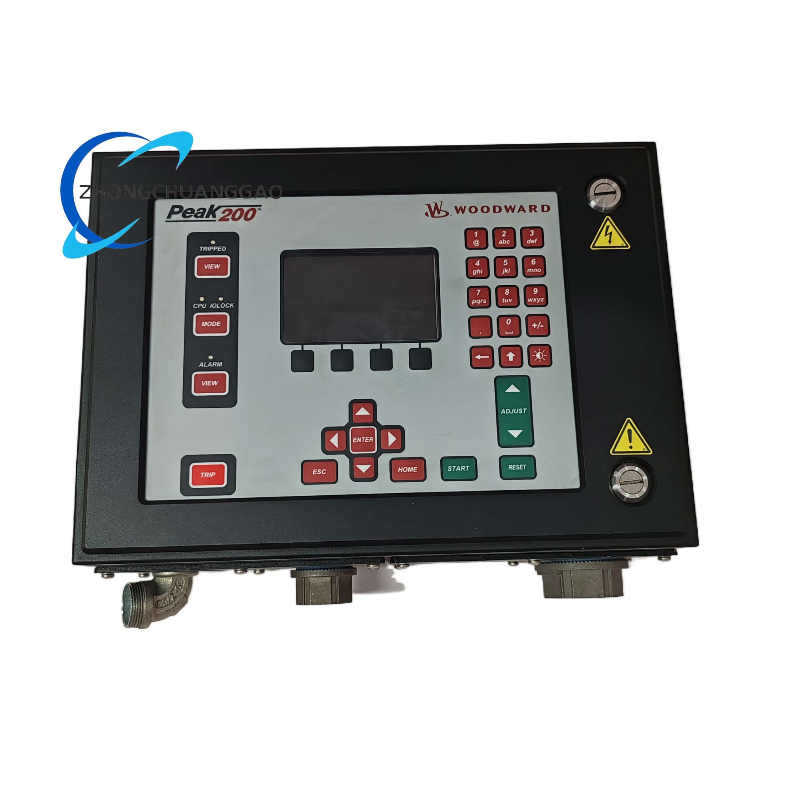
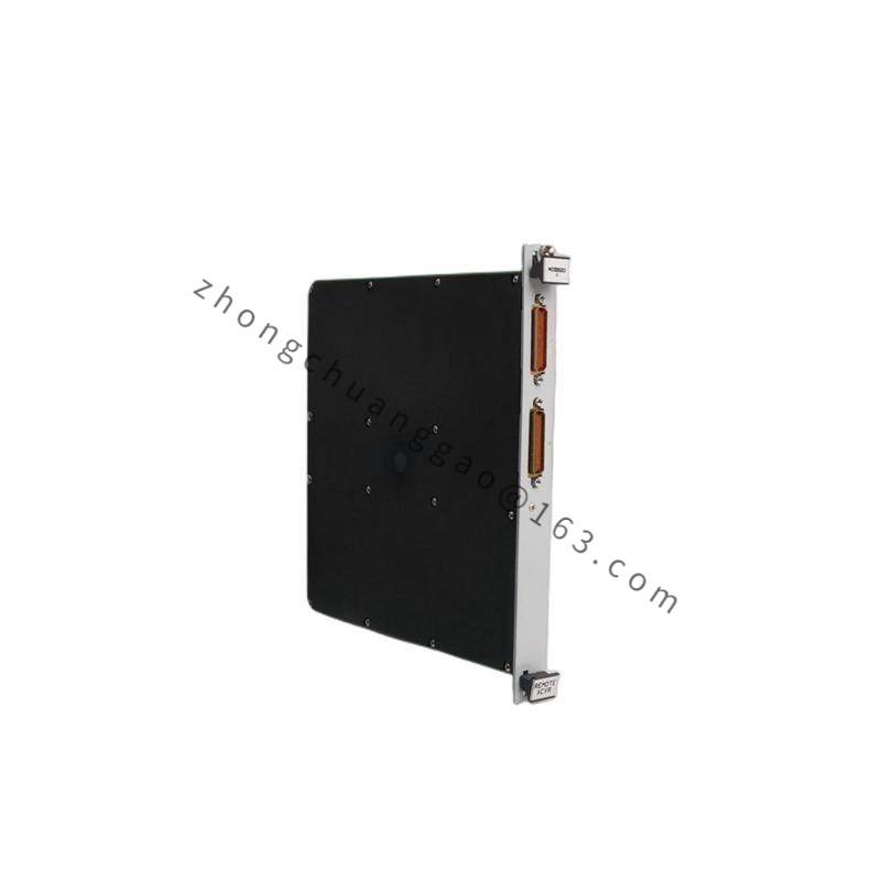
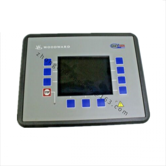
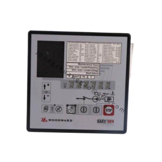
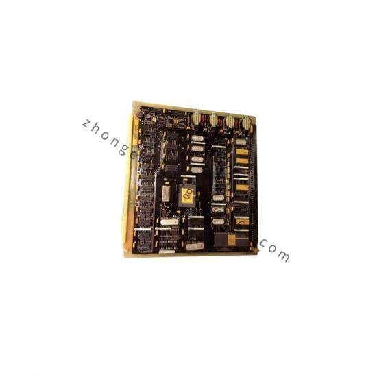
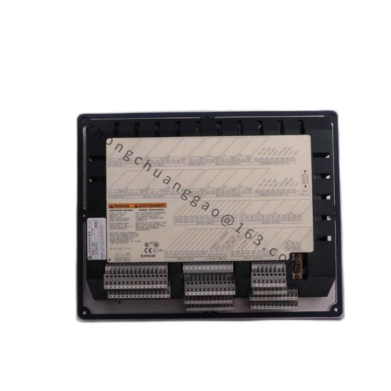
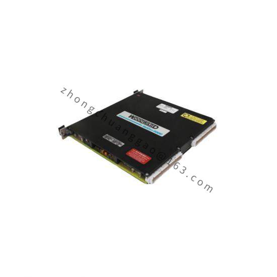
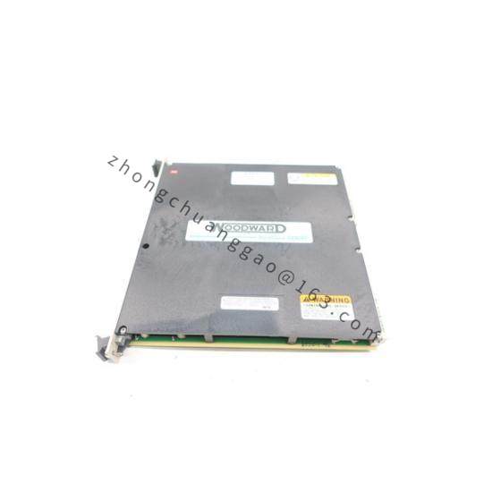
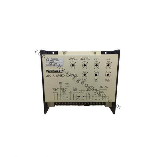
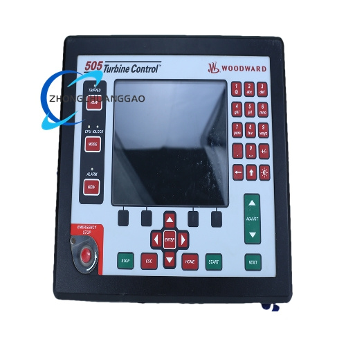
Product Name: Woodward 9906-739 Speed Control & Load Sharing Controller
Product Introduction: This controller acquires pulse signals from a magnetic speed pickup to calculate actual speed, performs a differential calculation with the set speed, and outputs a corresponding drive current to control the fuel actuator for fuel quantity adjustment. In multi-unit parallel operation, it reads the load signals of other units on the bus and dynamically adjusts the output to achieve uniform load distribution.
Power Supply: Must not exceed 40 VDC (overvoltage will burn out the power driver circuit)
Speed Sensing: Magnetic pickup pulse input
Drive Output: Proportional actuator drive current output
Operating Temperature: Industrial control cabinet internal application
Enclosure Rating: Must be installed inside a sealed industrial control cabinet; not directly mountable on the engine body
Functional Features:
Closed-loop speed control via magnetic pickup signal acquisition and differential calculation
Dynamic output correction based on load signals from other units on the bus for multi-machine parallel load sharing
Local fault status indication
Application Scenarios: Used in parallel control systems for generator sets driven by diesel engines, gasoline engines, steam turbines, or gas turbines.
Material Composition: Industrial-grade circuit board with power driver circuitry, housed in a metal enclosure.
Working Principle: Acquires pulse signals from the magnetic speed pickup to calculate actual speed, performs a differential calculation with the set speed, and outputs a corresponding drive current to control the fuel actuator for fuel quantity adjustment. In multi-unit parallel operation, it reads the load signals of other units on the bus and dynamically adjusts the output to achieve uniform load distribution.
Installation Requirements:
Must be installed inside a sealed industrial control cabinet; direct mounting on the engine body is prohibited
Keep away from strong electromagnetic interference sources such as high-voltage cables and contactors; maintain a distance of at least 15 cm from heat-generating devices
Vertical installation of the unit is required, with a maximum allowable tilt angle of ±45°; maintain a ventilation clearance of ≥30 mm around the unit
Speed sensors must use shielded twisted-pair cable, with the shield grounded at a single point (grounding at both ends is prohibited)
An independent disconnect switch must be configured inside the control cabinet as a power-down protection device
Usage Precautions:
Anti-static protection must be observed when assembling/disassembling circuit boards; static electricity will directly damage the chips on the board
Supply voltage must never exceed 40 VDC; overvoltage will burn out the power driver circuit
This controller does not include independent overspeed protection; the system must be equipped with an independent hardware overspeed shutdown device, and overspeed protection must not rely on this controller
Strictly distinguish power polarity during wiring; reverse connection will cause direct hardware damage
In humid or salt-spray environments, an additional moisture-proof and anti-corrosion control cabinet is required; the device body does not support direct outdoor use