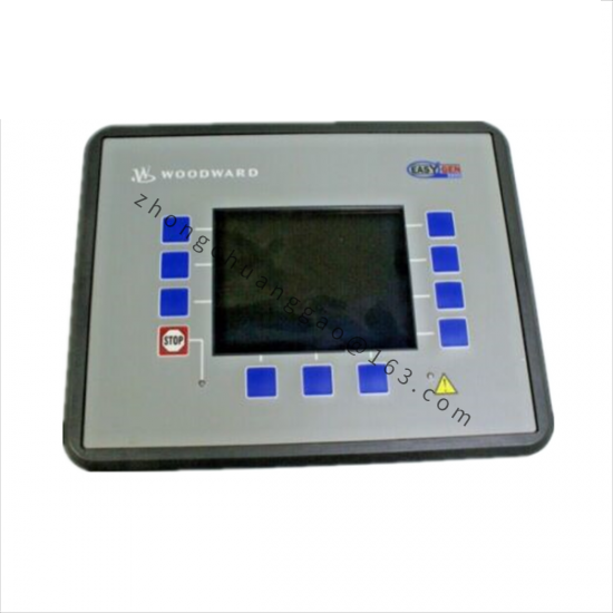
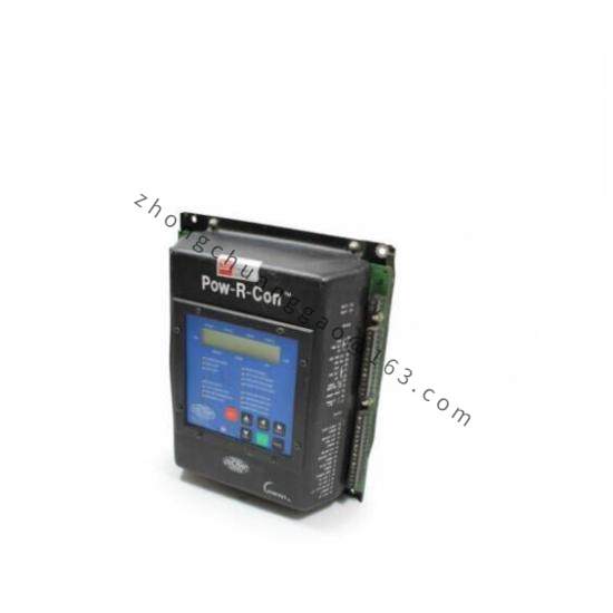
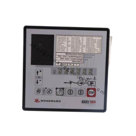
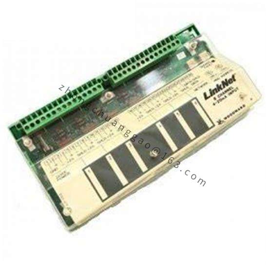
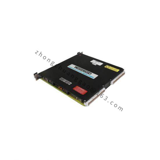
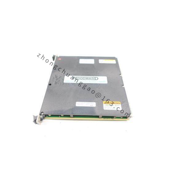
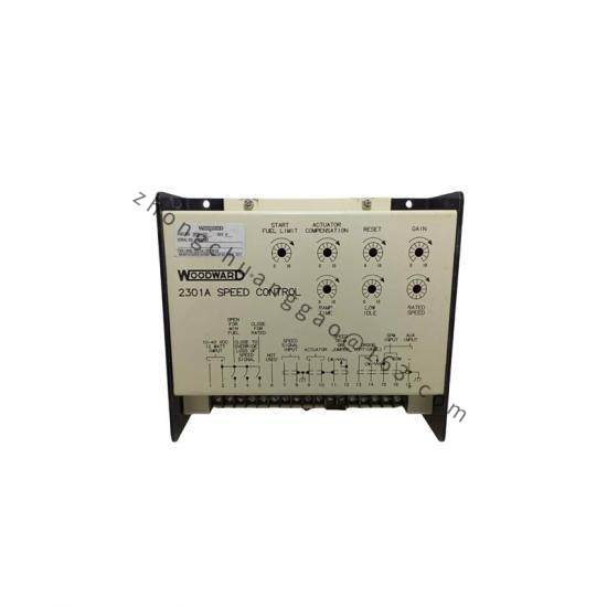
Product Introduction: The 9905-764 is a load-sharing module designed by Woodward for use with engines equipped with speed controls. It accepts ±3 Vdc speed-setting inputs, 0.5–4.5 Vdc inputs, or PWM (Pulse Width Modulation) inputs, enabling load sharing between engines fitted with non-Woodward speed controls and those controlled by Woodward electronic controls, or among multiple Woodward load-sharing modules.
AC Model Power Supply: Jumper-selectable 95–130 V or 190–260 V line-to-line, 50–400 Hz, approx. 10 W
Three-Phase PT Input: 95–130 V or 190–260 V line-to-line, 50–400 Hz; PT input load 1.6 W/phase at 240 V, 0.4 W/phase at 120 V
Three-Phase CT Input: 3–7 A full load; CT input burden 0.1 VA/phase
Load Share Input: 0–3 Vdc into 25 kΩ impedance in isochronous mode, open circuit in droop mode
Synchronizing Input: Compatible with optional Woodward SPM-A synchronizer
Output Speed Control: +0.5 to +4.5 Vdc analog, ±3 Vdc analog, or PWM (model dependent)
Weight: 0.95 kg
Functional Features: Provides isochronous and droop load-sharing capability for generator-set applications. Allows manual adjustment of output level via an external 10 kΩ potentiometer. An external droop switch is wired in series with the auxiliary breaker contact; when the droop switch or auxiliary breaker opens, droop mode is selected.
Application Scenarios: Generator-set load sharing; integration with Woodward SPM-A synchronizers, SPM-D synchronizers, Automatic Generator Load Control (AGLC), and Automatic Power Transfer and Load Control (APTL) within power generation control systems.
Structural Characteristics: Output I/O module form factor, 0.95 kg, suitable for control-panel mounting.
Working Principle: The module senses actual current via CT inputs and produces a DC output signal proportional to total sensed load, which is fed back to the speed control to achieve balanced load distribution across paralleled units.
Installation Requirements: Select DC or AC power model accordingly. For AC models, set the jumper for the correct voltage range (95–130 V or 190–260 V). Wire three-phase PT and CT inputs per system voltage and burden ratings. Connect the external droop switch in series with the auxiliary breaker contact.
Usage Precautions: Confirm whether a DC or AC powered version is required for the application. Verify CT polarity and phase sequence during commissioning to ensure correct load-share direction. Use only the specified external 10 kΩ potentiometer for manual output adjustment.