Product Name: Woodward 2301A Series Load Sharing and Speed Control (9905/9907 Series)
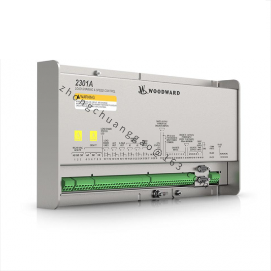
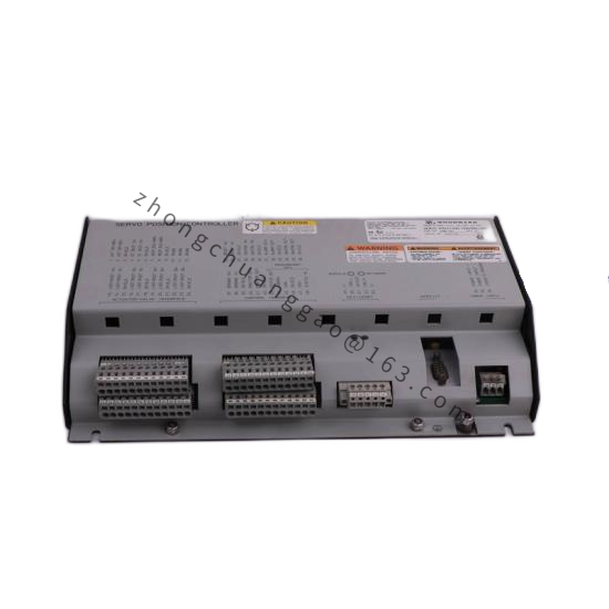
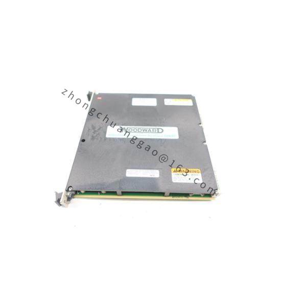
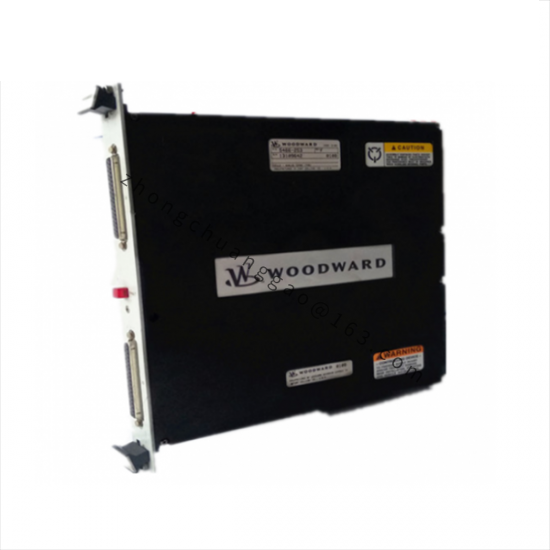
Product Introduction: The 9905-654 is a member of Woodward’s 2301A family of electronic load sharing and speed controls. These controls are designed to govern the speed and share load for generators driven by diesel engines, gas engines, steam turbines, or gas turbines. The 2301A control is housed in a sheet-metal chassis and consists of a single printed circuit board; all potentiometers are accessible from the front of the chassis.
Adjustable idle-to-rated speed linear ramps (0–10 seconds)
Start fuel limiting
Failed speed sensor protection
Four switch-selectable speed ranges
Forward- or reverse-acting configurations
Single or tandem actuator compatibility
Application Scenarios: Prime movers in generator sets, including diesel engines, gas engines, steam turbines, and gas turbines. Applicable in industrial power generation, marine propulsion systems, and auxiliary power systems.
Working Principle: The 2301A uses a proportional-integral (PI) control loop to regulate engine performance. It compares the frequency of the MPU (Magnetic Pickup) signal (actual speed) against an internal reference (desired speed). If a deviation occurs, it sends a current correction to the actuator. In paralleled applications, the unit continuously monitors the “Load Share” signal lines, comparing its own load output against the load share bus average and adjusting fuel delivery accordingly.
Installation Requirements:
Install in a “closed electrical operating area” or enclosed industrial control cabinet
Ensure adequate ventilation space for heat dissipation and maintenance access
Protect from direct contact with water or environments prone to condensation
Avoid proximity to high-voltage or high-current equipment that generates electromagnetic interference
Avoid vibration; the controller must not be mounted on the engine itself
Select a mounting location with an operating temperature range of –40 °C to +70 °C
Use shielded wiring for all speed, load-sharing, and actuator signal lines; terminate the shield at the cabinet ground bus only
Ensure correct MPU polarity wiring to avoid unstable governing
Usage Precautions:
The engine, turbine, or other prime mover must be equipped with an overspeed shutdown device that is totally independent of the prime mover control system
Observe ESD precautions when handling the control; use anti-static measures and avoid touching PCB components directly
Do not force front-panel potentiometers past their mechanical end-stops
Verify the latest manual revision on the Woodward website before installation and operation