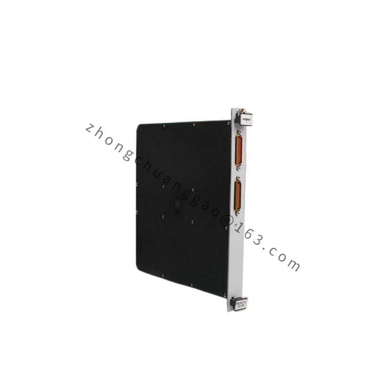
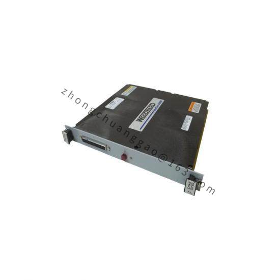
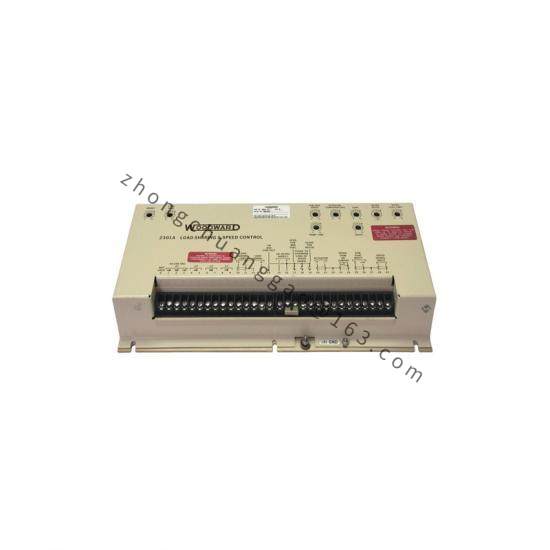
Product Name: 2301A Electronic Load Sharing and Speed Control (Low-Voltage Configuration)
Overview: Part of Woodward’s 9905 series 2301A analog electronic load sharing and speed controls for prime movers. It performs speed governing and load sharing for generators and turbines, receiving magnetic pickup speed sensor signals and delivering actuator drive output for closed-loop speed control. The 9905 series low-voltage variant operates on 20–40 VDC.
Operating Temperature: –40 to +85 °C (–40 to +185 °F)
Vibration: 4 Gs, 5–500 Hz
Shock: 60 Gs
Weight: Approx. 1.8 kg (4 lb)
Finish: Gloss powder coat
Compliance: CE Mark (EMC Directive 89/336/EEC, Low Voltage Directive 73/23/EEC); UL Listed for Ordinary Locations (6IN6)
Features: Switch-selectable speed ranges; isochronous and droop modes via terminal 14 contact control; load sharing with ±5% of rated load accuracy when speed settings are matched; forward/reverse acting support; soft acceleration ramp; actuator compensation time constant compatibility 0–500 ms; amplifier gain reset (stability) and load gain adjustments; optional SPM-A synchronizer interface via terminals 25–26.
Applications: Speed governing and load sharing for turbine-driven generators; parallel operation of multiple generating units; industrial steam turbines; gas and diesel engine prime movers.
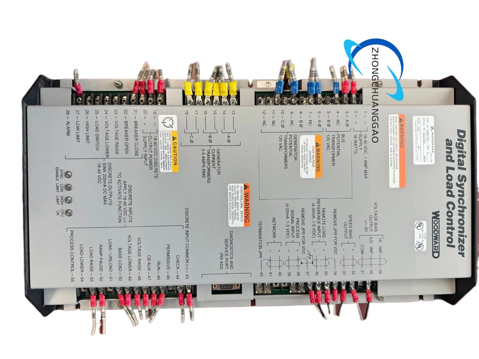
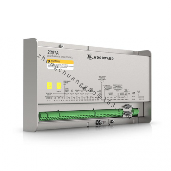
Structure: Panel-mount industrial control with terminal strip connections (terminals 0, 14, 16, 17, 18, 19, 23, 24, 25, 26, etc.). High-voltage models provide +20 VDC on terminal 0 for input terminals 14, 17, 18, 19, 30; low-voltage models provide DC source on terminal 16.
Working Principle: The magnetic speed sensor signal is conditioned and compared against the speed setpoint. The PID-type analog control drives the actuator output to maintain speed. In isochronous mode (terminal 14 closed), load sharing lines are active for parallel operation. In droop mode (terminal 14 open), load sharing lines are disabled. The SPM synchronizer optionally biases speed for bus matching. Using the wrong speed range can cause overspeed resulting in equipment damage or personal injury/death; the speed range is factory-set for 2000–6000 Hz and must be changed per the manual.
Installation & Precautions: Before disconnecting a battery from a control system using an alternator or battery-charging device, ensure the charging device is turned off to prevent system damage. Electronic controls contain static-sensitive parts — discharge body static before handling, avoid vinyl/styrofoam near PCBs, and handle PCBs only by their edges. Do not use the minimum fuel contact option as part of any emergency stop sequence. Verify correct speed range selection to prevent possible overspeed.