Product Name: Fuel Bypass Three-Way Hydraulic Control Valve Assembly
Overview: A hydraulically driven three-way fuel bypass control valve adapted for gas turbine liquid fuel systems. It receives hydraulic control oil signals to achieve fuel flow distribution and switching between the main path and bypass, regulating fuel return flow and stabilizing fuel supply pressure. Integrated with LVDT valve position feedback for continuous proportional control. Used for pressure stabilization control in heavy oil and diesel fuel supply systems.
Pressure Regulation Fluctuation: ≤±1% of rated supply pressure
Features: Three-way flow channel integral design simultaneously completing fuel inlet, supply, and return bypass flow distribution; coaxial LVDT displacement sensor acquiring spool position in real time for closed-loop proportional control; built-in spring fail-safe return shifting the valve to the safe bypass position upon loss of drive oil pressure; spool with wear-resistant hardening treatment suitable for industrial fuel oil with micro-impurities; flow channels optimized through flow-field analysis with strong pressure fluctuation suppression capability for high fuel supply pressure stability.
Applications: Gas turbine liquid fuel supply bypass regulation; fuel pressure stabilization control for heavy oil units; industrial turbine fuel system flow distribution; standby diesel fuel circuit regulation.
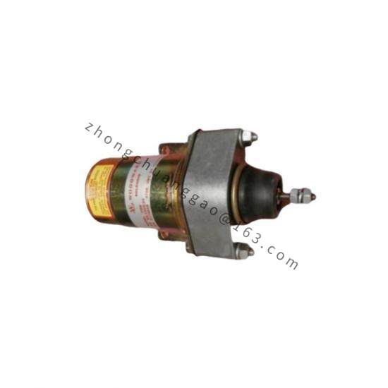
Structure: Three-way integral valve body with three flanged interfaces respectively for fuel inlet, supply, and return bypass; hydraulic drive cylinder and LVDT sensor assembly mounted on top; drive oil port on the side of the body; internally integrated return spring assembly; the hydraulic drive chamber and fuel media chamber adopt isolated sealing structure to avoid media cross-contamination.
Working Principle: External hydraulic control oil enters the drive cylinder, pushing the spool to linear displacement. The spool changes the opening area of the internal flow passage of the three-way valve, distributing the fuel flow to the combustor and the bypass flow returning to the tank. The LVDT acquires the actual spool position and feeds back to the turbine control system, forming closed-loop regulation. Upon loss of drive oil pressure, the internal spring pushes the spool back to the bypass fully-open safe position, cutting off fuel supply to the burner.
Installation & Precautions: The body must be installed strictly following the flow direction marking; the three pipelines must not be misconnected. The fuel pipeline must be equipped with a filter of no less than 10 μm precision. The valve body must not bear pipeline thermal expansion stress; expansion joints must be added to the pipeline. The LVDT signal cable must use twisted-pair shielded cable, with the shield grounded at a single point on the control cabinet side. Connect the valve body flanges only after the pipeline completes circulation flushing and passes acceptance.