
Woodward 9902-222
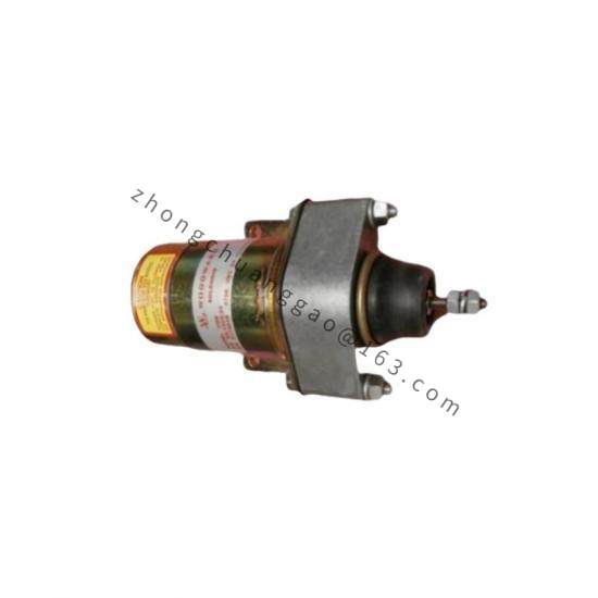
Product Name: 3055 VSV Servovalve
Product Introduction: The 9902-222 is the 3055 VSV (Variable Stator Vane) Servovalve, documented in Woodward manual 40124. It is a torque-motor-driven two-stage servovalve designed for hydraulic control of VSV actuators on gas turbines. It converts an electrical command signal from the turbine control system into a precisely metered hydraulic flow to position the VSV actuator, preventing compressor stall and optimizing part-load efficiency.
Detailed content
Technical Specifications: Detailed hydraulic flow ratings, pressure limits, and torque motor current parameters are provided in Woodward manual 40124 (3055 VSV Servovalve and VSV Actuators — Installation and Operation Manual). The servovalve is designed for use with MIL-L-23699 or MIL-L-7808 turbine engine lubricating oil.
Functional Features:
-
Two-stage servovalve with torque motor first stage and pilot valve / power stage
-
Integrated check valve and accumulator interface
-
Precisely metered hydraulic output for closed-loop VSV actuator positioning
-
Designed for direct mounting onto the VSV hydraulic pump (using kit 8924-874) or as a standalone servovalve in dual-servovalve configurations
Application Scenarios: Non-aero industrial gas turbines requiring variable stator vane positioning; GE LM-series aero-derivative gas turbines; compressor anti-stall control; part-load efficiency optimization.
Structural Characteristics: The servovalve comprises a torque motor, a pilot stage, a main spool, and an integral LVDT (Linear Variable Differential Transformer) feedback element in the associated actuator. The valve body is constructed of aluminum with through-hardened stainless steel internal parts. Hydraulic ports are clearly marked (ROD, HEAD, ACC).
Working Principle: The electronic controller outputs a current command to the torque motor. The torque motor deflects the pilot stage, directing pilot flow that shifts the main spool. The main spool meters hydraulic supply pressure to either the rod or head side of the VSV actuator, driving the output shaft. The integral LVDT feeds actuator position back to the final driver, closing the position control loop. An optional accumulator connected to the “ACC” port provides emergency stroking capability should the hydraulic pump fail.
Installation Requirements: Use kit 8924-874 for direct mounting onto the VSV hydraulic pump — this kit includes O-rings, bolts, and washers. Align the serrated drive shaft of the tachometer pump carefully for unencumbered rotation. Use a lifting strap and hoist for lifting and moving the control. Connect hydraulic lines per the outline drawing, observing ROD / HEAD / ACC port markings. Filters and screens in the system must be in place to prevent contamination of essential orifices.
Usage Notes: Read the entire manual 40124 and all related publications before installing, operating, or servicing. The engine/turbine must be equipped with an independent overspeed shutdown device. Personal protective equipment must be worn. Be prepared to make an emergency shutdown when starting the turbine. Do not modify the equipment or operate outside specified mechanical, electrical, or hydraulic limits. Observe ESD precautions when handling associated electronic controls.
Woodward 9902-338
Product Name: VSV / IGV Servovalve and Actuator System Component
Product Introduction: The 9902-338 is part of Woodward’s Variable Stator Vane (VSV) and Inlet Guide Vane (IGV) electro-hydraulic control product family, documented in Woodward manual 40136 (Dual Servovalve and VSV and IGV Actuators — Installation and Operation Manual). Within the 9902 VSV/IGV product line, 9902-338 serves as a hydraulic control component for positioning compressor variable geometry on gas turbines. The dual servovalve design enables simultaneous, independent control of IGV and VSV actuators from a single hydraulic pump.
Technical Specifications: Detailed specifications for the 9902-338 configuration (hydraulic flow rating, torque motor current, pressure class) are provided in Woodward manual 40136. Each actuator in the system can provide up to 3.445 inches (87.50 mm) of output stroke. The servovalve and actuators operate with MIL-L-23699 or MIL-L-7808 turbine lubricating oil.
Functional Features:
-
Dual, identical torque-motor servovalve stages — one dedicated to IGV, one to VSV
-
Separate final drivers (part number 8924-874) for IGV and VSV channels
-
Closed-loop position control via integral LVDT feedback in each actuator
-
Optional accumulator port (“ACC”) for fail-safe stroking capability
-
Integrated filters and screens to prevent contamination
Application Scenarios: Gas turbine compressor variable stator vane and inlet guide vane control; anti-stall protection; part-load efficiency optimization; GE LM-series and other industrial gas turbines.
Structural Characteristics: The servovalve features an aluminum case with through-hardened stainless steel internal parts. Hydraulic ports marked “ROD” and “HEAD” are provided for both IGV and VSV actuators. Each actuator integrates an LVDT for position feedback. The servovalve is designed to be installed, with kit 8924-874, directly over the hydraulic pump, with supply and drain feeding through the base of the servo to the pump.
Working Principle: A hydraulic pump provides pressure to the dual servovalve. The electronic package sends separate command signals to the IGP and VSV torque motors. Each torque motor deflects its pilot stage, metering hydraulic flow to the respective actuator’s rod or head side. The actuator output shaft connects to the hardware on the inlet guide vanes and variable stator vanes. The LVDT in each actuator provides a position-proportional electrical signal back to the final driver, closing the position control loop.
Installation Requirements: Install the servovalve directly over the hydraulic pump using kit 8924-874 (includes O-rings, bolts, washers). Connect hydraulic ports ROD and HEAD to the correspondingly marked ports on each actuator. Connect the ACC port to an external accumulator if fail-safe stroking is required (accumulator not provided by Woodward). Ensure system filtration is in place. Follow the receiving, storage, and installation procedures in Chapter 2 of manual 40136.
Usage Notes: Read the entire manual 40136 and all related publications before installation, operation, or servicing. The turbine must have an independent overspeed shutdown device. Use proper PPE. Be prepared for emergency shutdown during start-up. Do not operate outside specified hydraulic, electrical, or mechanical limits. Observe ESD precautions for associated electronic controls.