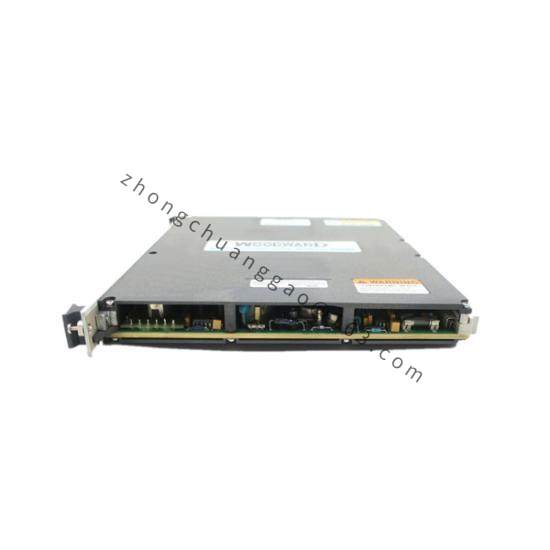
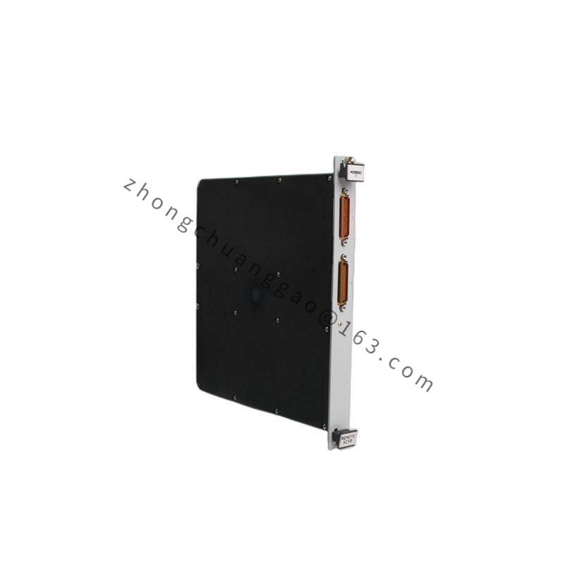
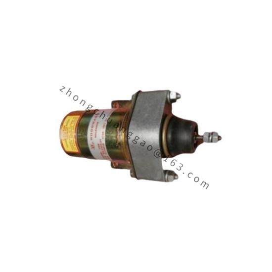
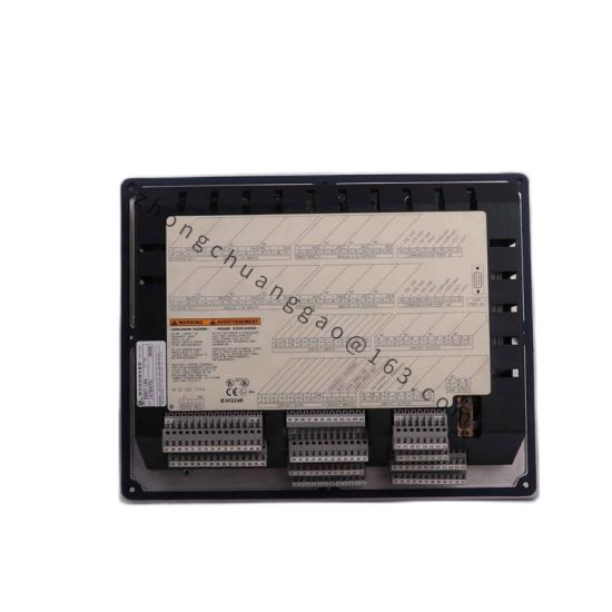
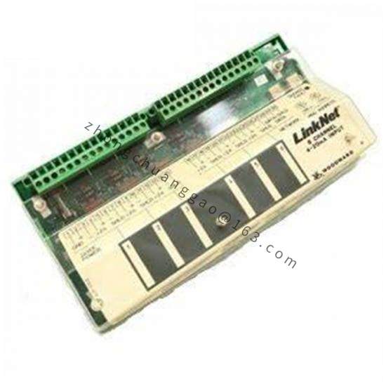
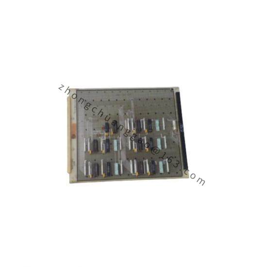
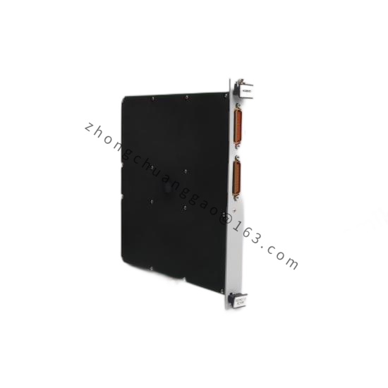
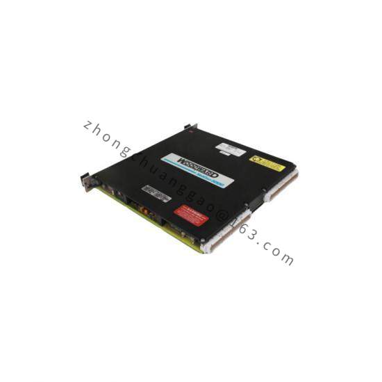
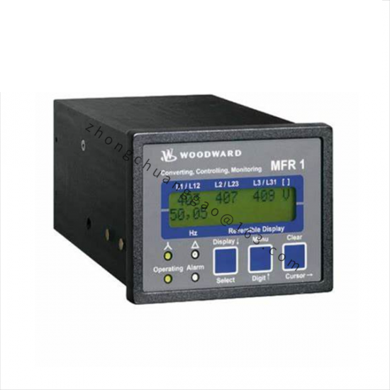
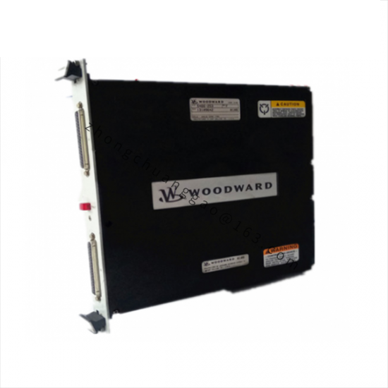
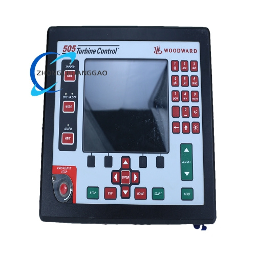
Woodward 9566-850
Model: 9566-850
Product Name: ProAct Digital Speed Control System
Product Introduction: The ProAct is a microprocessor-based governor for diesel, gas and dual-fuel engines. It regulates speed through PID control, interfaces with magnetic or Hall speed sensors, and drives electronic actuators for generator, marine and compressor applications.
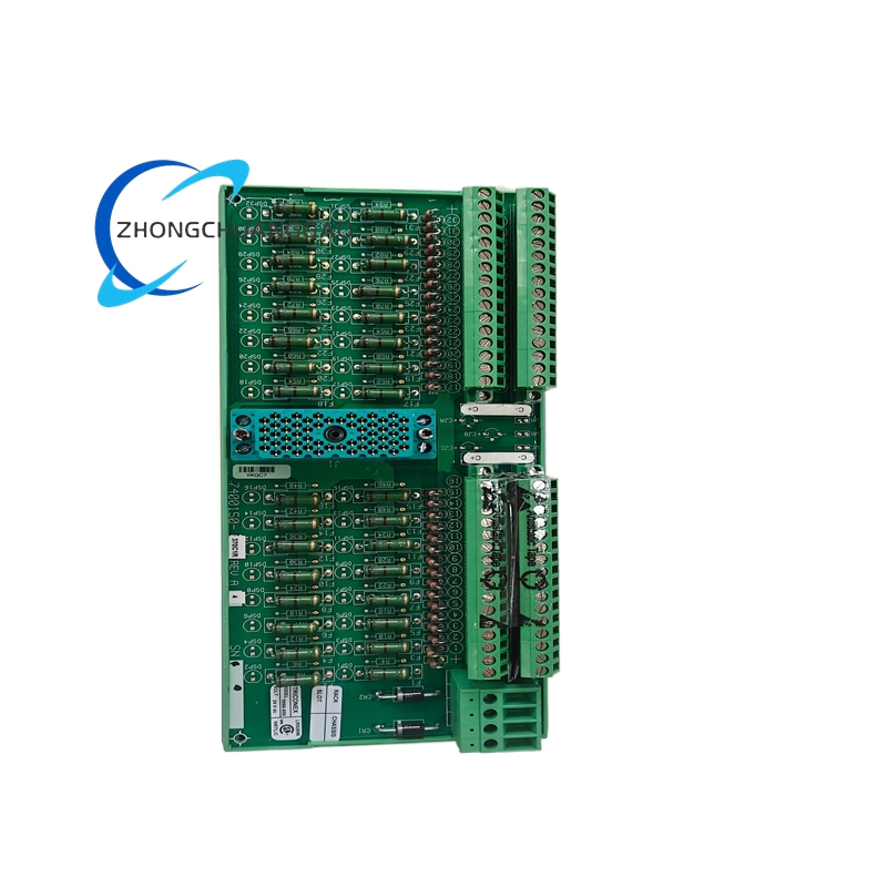
Detailed content
Technical Specifications:
- Control Type: Digital PID with isochronous and droop modes
- Speed Regulation: ±0.25% isochronous; droop adjustable 0-10%
- Supply Voltage: 18-32 V DC nominal, 12-36 V DC operating range
- Power Consumption: 15 W maximum
- Speed Sensing: Magnetic pickup or Hall-effect sensor
- Actuator Output: PWM actuator drive and 0-200 mA current output
- Communication: RS-485 Modbus RTU
- Operating Temperature: -40°C to +70°C
- Protection Rating: IP54, NEMA 12 equivalent
- Indicators: LED status and fault diagnostics
- Mounting: DIN rail or panel mount
Functional Features:
- Load Sharing: Droop mode for parallel generators without external load-sharing hardware
- Overspeed Protection Logic: Configurable overspeed shutdown and underspeed alarm
- Actuator Compatibility: Rotary, linear and stepper actuators
- Self-Diagnosis: Speed loss, actuator fault, sensor fault and communication error reporting
Application Scenarios:
- Generator Sets: Prime and standby power with frequency control
- Marine Propulsion: Main engine and auxiliary engine governing
- Compressor and Pump Drives: Constant-speed or load-following industrial prime movers
- Oil and Gas Skids: Pipeline compression, wellhead auxiliaries and drilling power
- Cogeneration: Heat-power balance with grid or island operation
Structural Characteristics:
- Enclosure: Industrial metal/plastic control housing with sealed connectors
- Terminals: Labeled power, speed sensor, actuator and communication terminals
- Display: Status LEDs; some configurations use external programmer or PC software
Working Principle: The controller receives engine speed from an MPU or Hall sensor, compares actual speed with the setpoint, calculates PID correction and sends a PWM or current command to the actuator. In droop mode, speed setpoint decreases proportionally with load to enable stable parallel operation.
Installation Requirements:
- Mount in low-vibration location with ventilation.
- Supply 18-32 V DC from a regulated engine battery/charger circuit.
- Install MPU at correct air gap on flywheel or gear train.
- Ground the controller chassis and shield sensor cables.
Usage Precautions:
- Do not operate outside 12-36 V DC.
- Calibrate actuator end points before load acceptance tests.
- Verify overspeed trip settings during commissioning.
- Protect RS-485 termination and grounding to avoid bus communication faults.