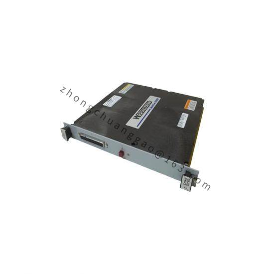
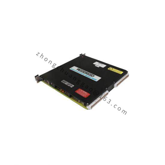
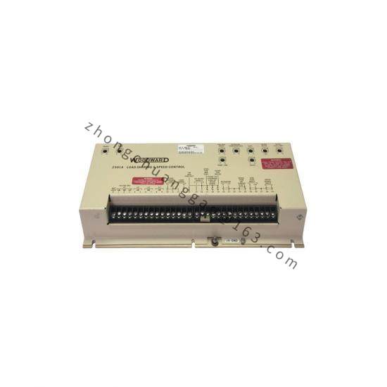
Product Description: The 8915-912 is a 1907 Large Liquid Valve and Actuator assembly for gas turbine liquid fuel metering. It is functionally identical to other 1907 Large Liquid Valve & Actuator assemblies in the Woodward 8915 series, providing precision fuel metering with integrated electric actuation.
Differential Pressure: 345 to 827 kPa (50 to 120 psig)
Fuel Viscosity: 0.5 to 12.0 centistokes
Fuel Specific Gravity: 0.77 to 0.91
Cleanliness: 20 μm filtration, water ≤0.1%, particulates ≤1.0 mg/L
Fuel Compatibility: Broad compatibility with diesel, kerosene, gasoline, light and heavy distillates, naphtha, gas turbine fuels, fuel oils, and biodiesel (FKM compatible).
Functional Features:
Constant pressure drop metering via integral differential pressure regulator
Fuel flow unaffected by discharge pressure or inlet flow variations
Available in various flow ranges selected per installation requirements
Application Scenarios: Industrial gas turbine liquid fuel metering for power generation, oil & gas production, marine propulsion, and aviation gas turbine service.
Material Composition: Aluminum or stainless steel valve body; through-hardened stainless steel internal components; FKM elastomeric seals.
Structural Characteristics: The 1907 valve comprises a hollow plunger within a ported sleeve, held by a spring against the input lever. The metering port size and shape are determined by turbine fuel-flow requirements. When paired with EM-35 actuator, the assembly includes a resolver for precise position feedback.
Working Principle: The electrical actuator receives position commands from the control system and drives the fuel valve plunger. The differential pressure regulator maintains constant pressure drop across the metering port, ensuring fuel flow at any given valve position remains constant despite variations in system pressure.
Installation Requirements:
Install valve square with governor/actuator linkage to prevent binding
Allocate actuator travel: approximately two-thirds between minimum and maximum fuel stops
Split remaining travel between maximum and minimum ends to assure positive shutdown and maximum fuel positions
Use shielded wiring per Woodward control wiring diagrams
Follow outline drawing for dimensional and porting requirements