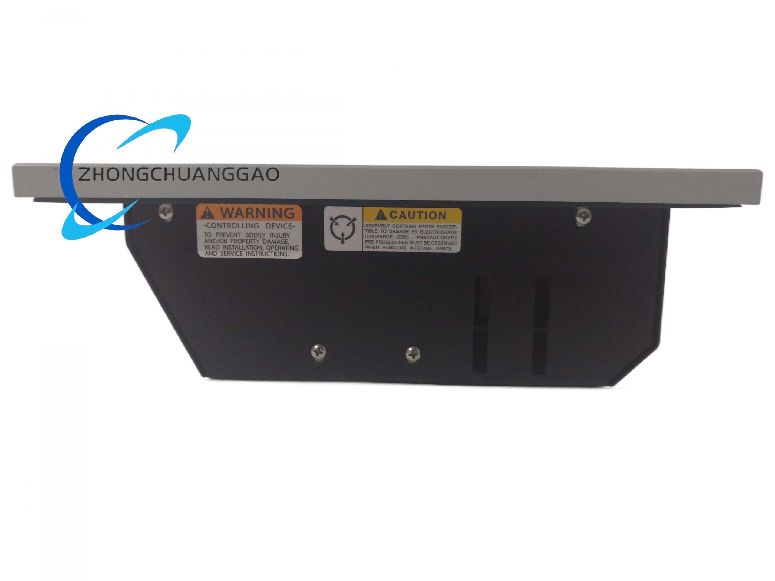
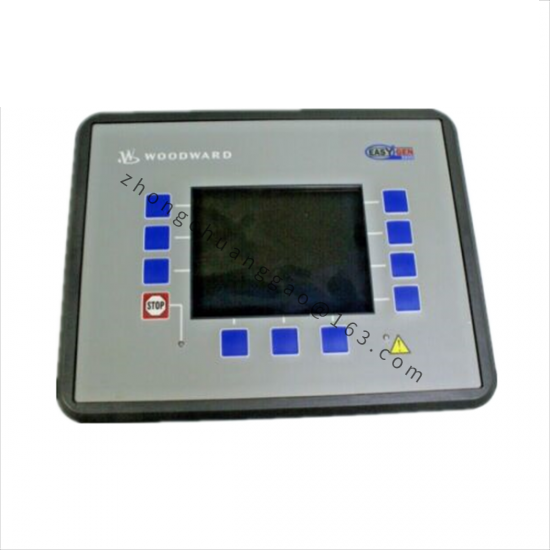
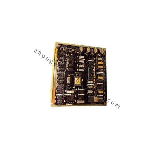
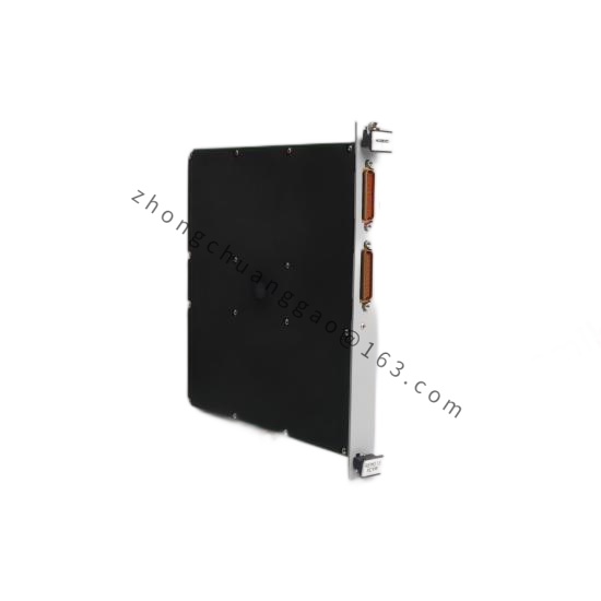
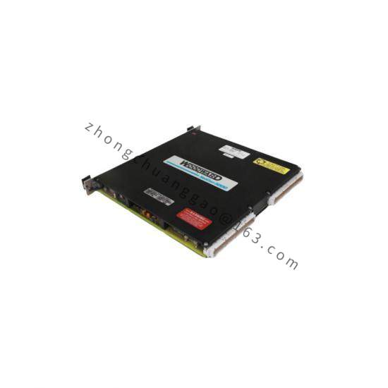
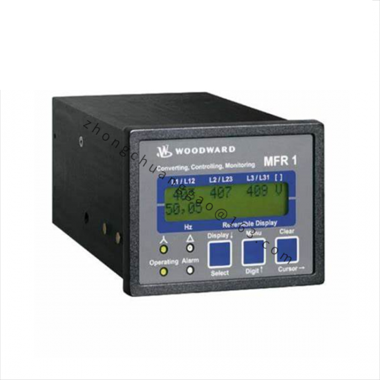
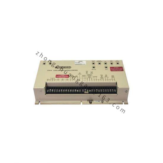
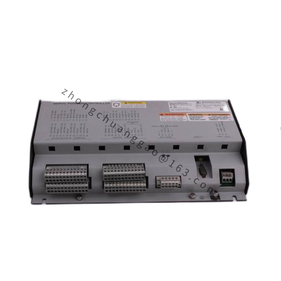
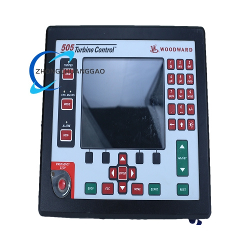
Product Description: The 8915-883 is listed in Woodward parts documentation as a 1907 Large Liquid Valve & Actuator assembly for gas turbine liquid fuel metering. Note: Some third-party resellers describe this part generically as a “digital microprocessor controller module for industrial turbines,” but the authoritative Woodward parts catalog identifies it as a 1907 Large Liquid Valve & Actuator. The technical profile below reflects the 1907 valve and actuator assembly configuration.
Full-range valve positioning via integrated actuator
Multiple flow range configurations available
Application Scenarios: Gas turbine liquid fuel control in power generation, oil & gas, petrochemical, and marine industries.
Material Composition: Aluminum or stainless steel valve body; through-hardened stainless steel internals; FKM elastomer seals.
Working Principle: The integrated actuator positions the 1907 valve’s hollow plunger within the ported sleeve. The built-in differential pressure regulator maintains a constant pressure drop across the metering port, delivering fuel flow that remains constant regardless of discharge pressure or inlet flow variations.
Installation Requirements:
Install valve square with governor/actuator linkage to prevent binding
Allocate actuator output: approximately two-thirds between minimum and maximum fuel positions
Split remaining travel between max and min ends for positive shutdown and maximum fuel assurance
Use shielded wiring for electrical connections
Follow Woodward outline drawings for dimensional compliance
Usage Precautions:
Maintain fuel filtration at 20 μm absolute or finer
Limit water content to 0.1% by volume; solids/sediment to 1.0 mg per liter
Read this entire manual and all other publications pertaining to the work before installing, operating, or servicing
Practice all plant and safety instructions and precautions
Failure to follow instructions can cause personal injury and/or property damage