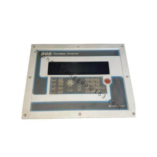
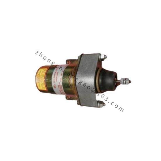
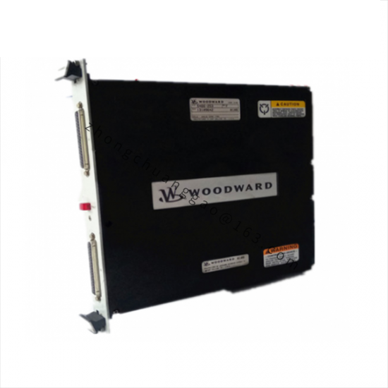
Product Description: The 8915-864 is a 1907 Large Liquid Valve and Actuator assembly for precision gas turbine liquid fuel metering. It is functionally equivalent to the 8915-815 and 8915-839 assemblies, comprising the 1907 large liquid fuel valve with an integrated TM-55 integrating actuator or equivalent positioning mechanism.
Differential pressure regulation for constant flow delivery
Exact valve positioning across full range of demands when paired with Woodward electronic control
Hazardous area certification (Class I, Div 1) for the TM-55 actuator variant
Application Scenarios: Gas turbine liquid fuel control in hazardous environments, power generation, oil & gas production, marine propulsion.
Material Composition: Aluminum or stainless steel valve body; through-hardened stainless steel actuator internals; FKM seals.
Working Principle: The electronic control sends a signal to the TM-55 actuator, which converts the electrical signal into hydraulic pressure causing mechanical response to position the fuel valve. An electrical position feedback transducer reports the exact location back to the control system, forming a closed loop.
Installation Requirements:
Read entire manual and all related publications before installing
Practice all plant and safety instructions
Use proper hydraulic fluid per specifications
Install valve square with actuator linkage to prevent binding
Allocate actuator travel: two-thirds between min/max, remaining third split at endpoints
Follow outline drawing for dimensional requirements
Usage Precautions:
Maintain fuel filtration at 20 μm or finer
Limit water content to 0.1% by volume; solids to 1.0 mg per liter
Any unauthorized modifications or use outside specified limits constitutes misuse, voids warranty, and invalidates certifications
Failure to follow instructions can cause personal injury and/or property damage