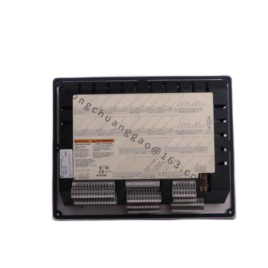
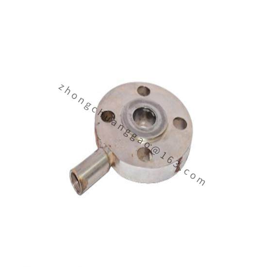
Woodward 8915-698
Product Name
3103 Gas Valve with TM-55 Actuator (3103/TM55 configuration).
Product Introduction
The 8915-698 is a Woodward configured package of the 3103 rotary sleeve gas metering valve with a TM-55 electro-hydraulic actuator, designed for industrial gas turbine fuel metering with high reliability and precise control.
Detailed content
Technical Specifications
-
Valve type: 3103 rotary sleeve-and-shoe throttling gas valve
-
Actuator type: TM-55 electro-hydraulic integrating actuator
-
Metered fuel: natural gas, propane, ethane, methane
-
Fuel specific gravity: 0.5 to 1.05
-
Gas flow range: 23 to 18 144 kg/h (50 to 40 000 lb/h) based on 0.6 sp gr
-
Inlet pressure: up to 5861 kPa (850 psig) per current Woodward 3103 manual; up to 6206 kPa (900 psia) in earlier published data; 4964 kPa (720 psia) maximum under CE marking restriction
-
Differential pressure: 172 to 5861 kPa (25 to 850 psig)
-
Fuel temperature: -40 to +149 °C (-40 to +300 °F)
-
Actuator hydraulic supply pressure: 2758 to 8274 kPa (400 to 1200 psig)
-
Actuator operating temperature: -40 to +121 °C (-40 to +250 °F)
-
Actuator input signal: ±200 mA integrating
-
Accuracy: ±5% of point, or ±0.25% of maximum flow, whichever is larger; ±2% of point at stops
-
Hydraulic fluid: mineral or synthetic based oil, diesel fuel, kerosene, gasoline, or light distillate fuel
-
Recommended viscosity: 6.0 to 400 cSt (150–200 SSU; ISO 32 grade)
-
Hydraulic cleanliness: ISO 4406 20/18/15 minimum
-
Supply filter: 40 μm nominal; external filtration 10 μm nominal required
Features
-
Self-cleaning metering structure adapts to sour (high sulfur) gas service
-
Through-hardened stainless steel internal parts resist wear and corrosion
-
Inlet guide tube directs contaminants through the metering port to minimize accumulation
-
Internal mechanical feedback provides excellent open-loop accuracy
-
Optional electrical position transducer for accurate position indication
-
Dual-coil (redundant) torque motor option available
-
Factory biased toward minimum fuel position on loss of supply pressure or input current (fail-safe)
-
Adapter housing provides adjustable maximum/minimum flow stops and an adjustable minimum position indicator switch
-
UL Listed and CSA Certified
Application Scenarios
-
Industrial gas turbine generator sets
-
Gas turbine driven compressors
-
Combined heat and power (CHP) systems
-
Mechanical drive gas turbines
-
Sour gas / high sulfur fuel environments
-
Offshore and marine gas turbine packages
Performance Parameters
-
Maximum flow capacity depends on available gas conditions
-
Minimum slewing time of the actuator: 100 ms; time constant: 25 ms
-
Shearing force at sleeve outer diameter exceeds 1334 N (300 lb) to cut through light debris such as pipe scale
-
Flow turndown ratios up to 500:1
Material Composition
-
Valve body: stainless steel
-
Internal parts: through-hardened stainless steel
-
Seals: Viton (FKM) or other fuel-compatible elastomer
-
Actuator case: anodized aluminum
-
Hydraulic fluid is sealed from the torque motor by a preformed packing ring
Structural Characteristics
-
Rotary sleeve-and-shoe metering structure, excellent flow characteristics
-
Two standard port configurations available, with maximum flow areas of 645 mm² (1 in²) and 1290 mm² (2 in²)
-
Actuator integrates torque motor servovalve, spring-centered four-land spool valve, and double-acting servo piston
-
Metering sleeve support bearings positively sealed from gas
-
Two overboard drains provided on the valve body
-
Valve angle indicator furnished on the valve
Working Principle
The electronic control sends an electric command to the TM-55 torque motor servovalve. The torque motor generates a differential pressure that operates the second-stage spool valve, regulating hydraulic oil flow to both ends of a double-acting servo piston. Piston motion rotates the output shaft, positioning the 3103 rotary metering sleeve to change the effective port opening area. An internal electrical position feedback transducer signals back to the control for closed-loop positioning. On loss of hydraulic supply or electrical input, the actuator spring biases the valve toward the minimum fuel position.
Installation Requirements
-
Handle with care; abuse can damage seals, installation surfaces, and factory adjustments
-
Keep plastic shipping caps on hydraulic and gas connections until piping is complete
-
Provide a 10 μm (nominal) filter in the hydraulic supply line; maintain ISO 4406 20/18/15 cleanliness
-
Use a pressure switch to confirm correct hydraulic supply pressure before start-up and continuously thereafter
-
Plumb one overboard drain outside the turbine enclosure; plug the unused drain (do not plug both)
-
Install with any attitude; installation attitude does not affect actuator performance
-
The TM-55 is factory calibrated and drained; no additional cleaning or calibration is required before installation
-
Ensure the prime mover is equipped with an independent overspeed shutdown device
Usage Precautions
-
Maintain strict hydraulic fluid cleanliness; contamination directly affects actuator life and performance
-
Control solid particle contaminants: <10 μm diameter ≤ 30 ppm by volume; >10 μm diameter ≤ 0.3 ppm by volume
-
Do not attempt field disassembly of the TM-55 actuator or 3103 valve. Woodward recommends factory service or authorized overhaul
-
Observe electrostatic discharge (ESD) precautions when handling electronic components
-
In hazardous (classified) areas, wiring must comply with applicable regional electrical codes