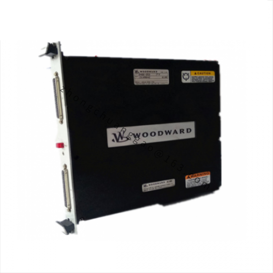
Product Name: Actuator and Valve Combined Unit (part number 8904-786)
Product Overview: The 8904-786 belongs to the Woodward 8904 series of actuator and valve combined units for gas turbine fuel systems. The combined unit is delivered pre-matched and calibrated from the factory for direct installation into turbine fuel systems, integrating an electro-hydraulic actuator with a gas valve.
Metering sleeve and gate: fully hardened stainless steel, precision-ground
Seals: fluorocarbon rubber (FKM) or other gas-resistant elastomers
Hydraulic seals: preformed packing rings to prevent magnetic contaminant accumulation
Structural Features: The actuator and valve are directly connected via an adapter with no intermediate transmission link. The rotary sleeve and gate metering structure provides excellent flow resistance characteristics. A dual-acting servo piston delivers powerful driving force. The hydraulic inlet fitting has a built-in 40 µm strainer for additional contamination protection. An electrical position feedback sensor is built into the actuator for closed-loop control. The overall structure is compact for easy installation within the turbine compartment.
Working Principle: The electronic controller sends an electrical command signal to the torque motor servo valve inside the actuator. The servo valve generates a pressure differential to drive the secondary spool, regulating the flow of hydraulic oil to the two ends of the dual-acting servo piston. The piston movement drives the final output shaft to rotate, thereby changing the opening of the valve metering sleeve. The built-in electrical position sensor detects the position in real time and feeds back to the controller, forming a high-precision closed-loop position control.
Application Scenarios:
Industrial gas turbine generator set fuel control
Gas compressor drive fuel management
Combined heat and power (CHP) system gas supply regulation
Distributed energy station gas flow control
Marine and offshore platform gas power units
Installation Requirements: Handle with care during lifting and installation to avoid damaging seals, mounting surfaces, and factory calibration settings. Protect hydraulic and gas connection ports with plastic caps or covers when not connected to formal piping. The actuator is delivered pre-calibrated and purged of calibration fluid, ready for installation without additional cleaning or calibration. Confirm hydraulic supply pressure is within the specified range before installation. Bleed trapped air from the hydraulic system to prevent abnormal initial operation. Configure a filter meeting requirements at the gas inlet. Use shielded cable for electrical connections with proper grounding.
Usage Notes: Hydraulic oil cleanliness is critical to actuator life; maintain the specified filtration grade (10 µm nominal). Strictly control gas impurity content. Regularly inspect hydraulic system pressure and oil condition. Avoid operation under overpressure, overtemperature, or out-of-range viscosity conditions. Periodically check electrical connector sealing and position feedback signal stability. Follow Woodward OEM recommendations for maintenance intervals; return to factory for overhaul upon expiry to restore to “like-new” condition.