Technical Specifications
Digital inputs: 8 channels, 24 VDC.
Digital outputs: 8 channels, 24 VDC positive-switching sourcing outputs.
Output switching type: high-side sourcing according to DIAS 8-output configuration.
Short-circuit protection: outputs are short-circuit-protected according to module design.
System integration: DIAS local bus or backplane according to controller configuration.
Functional Features
Reads 24 VDC sensor, pushbutton, limit switch and binary device signals.
Switches 24 VDC loads such as indicators, solenoids, relays and light loads.
Provides per-channel status indication according to DIAS I/O design.
Supports short-circuit and overload protection on output channels.
Fits compact DIAS I/O stations for machine and process control.
Performance Parameters
Input rating: 24 VDC standard industrial logic level.
Output rating: 24 VDC positive switching; verify per-channel current from exact DIAS order code.
Response depends on bus cycle and controller program scan configuration.
Operating environment must follow Sigmatek DIAS cabinet installation limits.
Material Composition
Module housing: industrial plastic or molded DIAS enclosure material.
PCB: FR4 with surface-mounted input and output electronics.
Terminals: DIAS front or side connectors according to station version.
Protection components: optoisolation and short-circuit protection devices according to channel design.
Structural Features
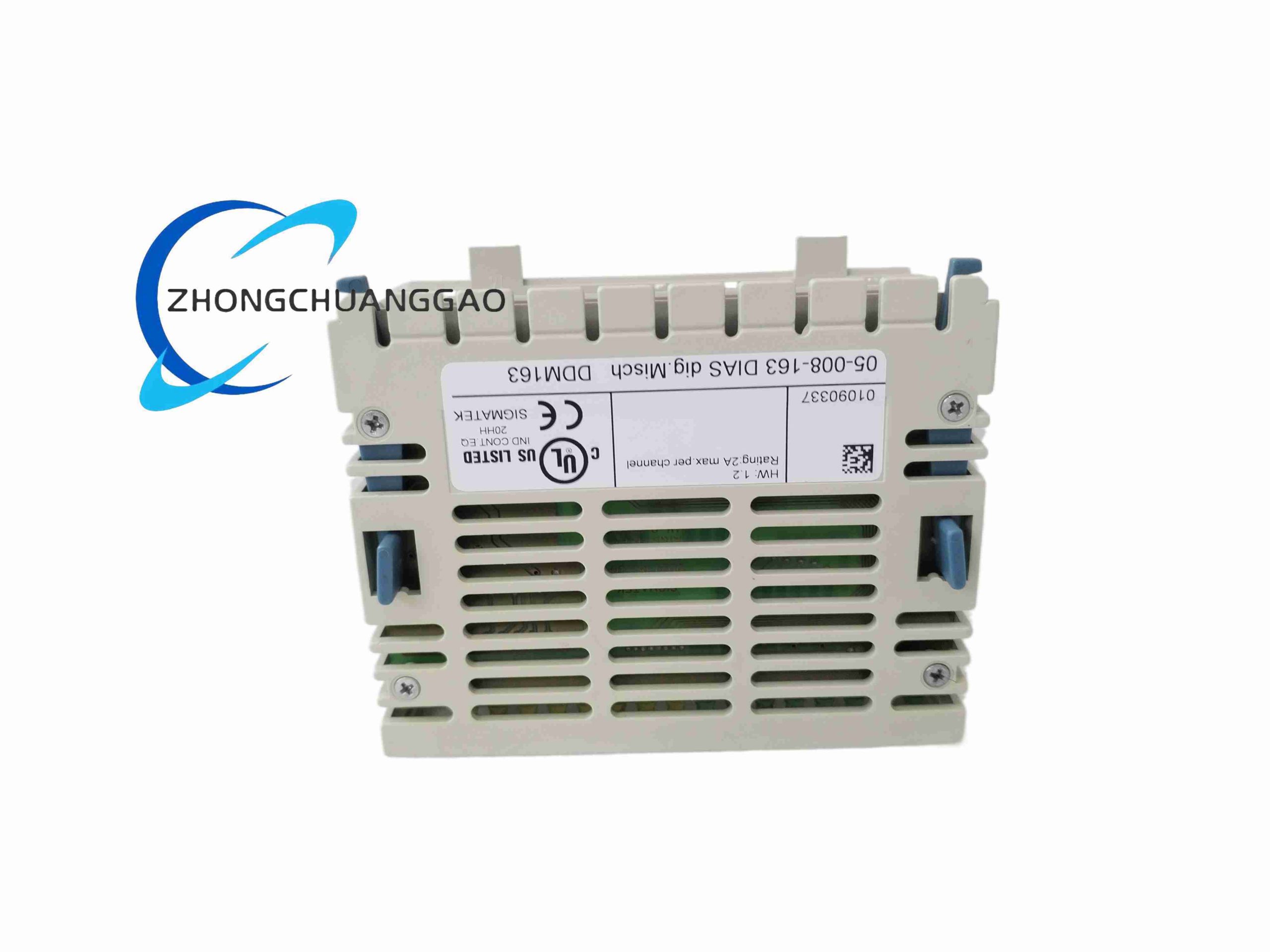
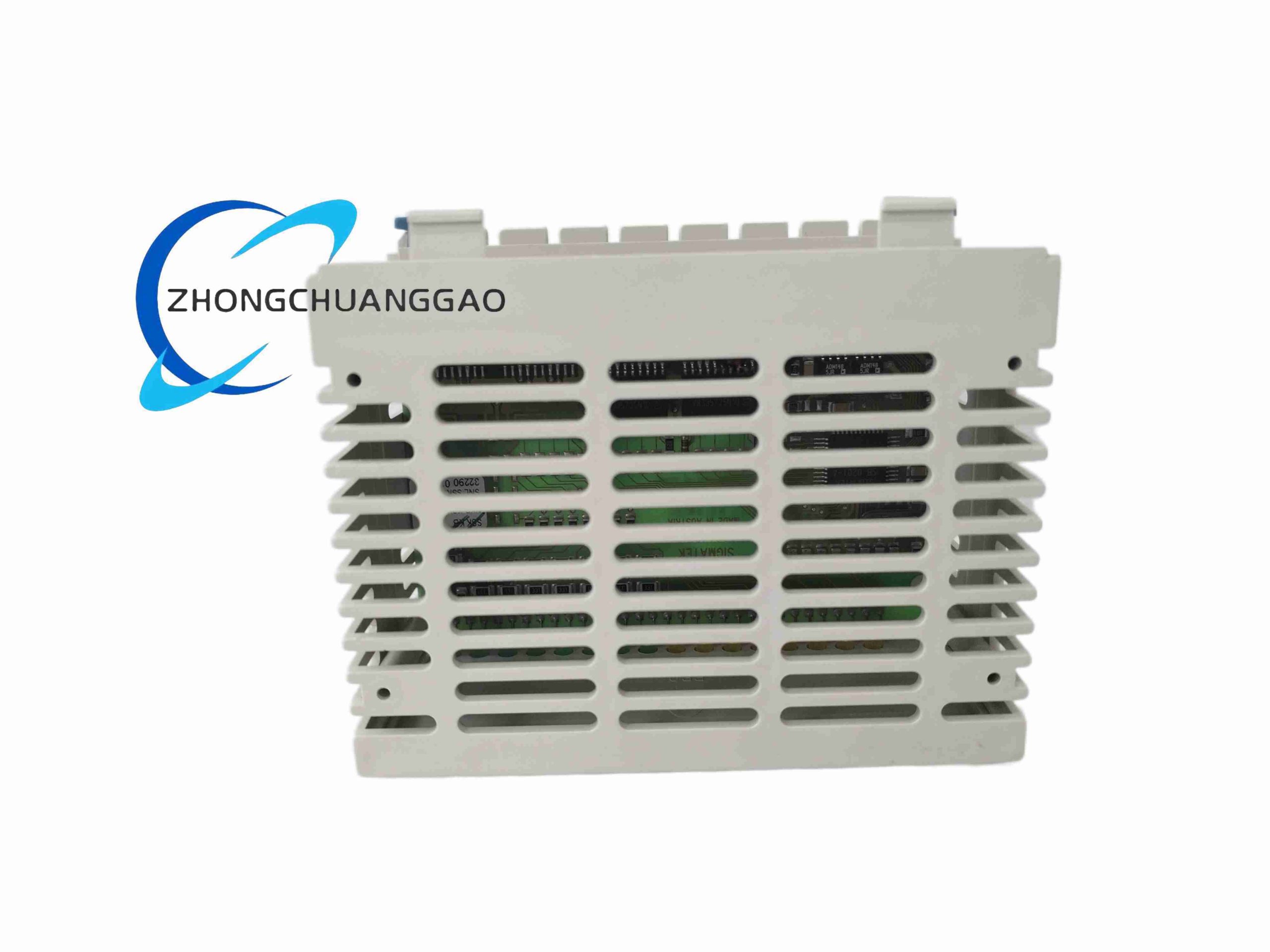
Slim DIAS slice or module format.
Separated input and output terminal groups.
LED indicators for power, input state and output state.
Bus connector for DIAS controller or neighboring I/O modules.
Working Principle
Each input channel detects 24 VDC presence and transfers the logic state to the DIAS bus. The controller program evaluates inputs and sends output commands to the module. Each output channel switches the 24 VDC supply to the load through a protected high-side driver, giving sourcing PNP-type logic to connected devices.
Installation Requirements
Install in a Sigmatek DIAS station or compatible bus carrier.
Use 24 VDC supply with correct polarity and current headroom.
Wire sensors to input group and loads to output group according to terminal diagram.
Ground and shield high-noise signal cables according to machine design.
Confirm DIAS firmware and station address before commissioning.
Usage Precautions
Do not exceed 24 VDC input or output rating.
Verify sourcing output type before replacing sinking-type modules.
Use interposing relays for high-inrush solenoids, contactors or inductive loads beyond module rating.
Add flyback diode or TVS suppression for inductive DC loads.
Do not remove or insert the module under power unless the DIAS system explicitly permits hot replacement.