Technical Specifications
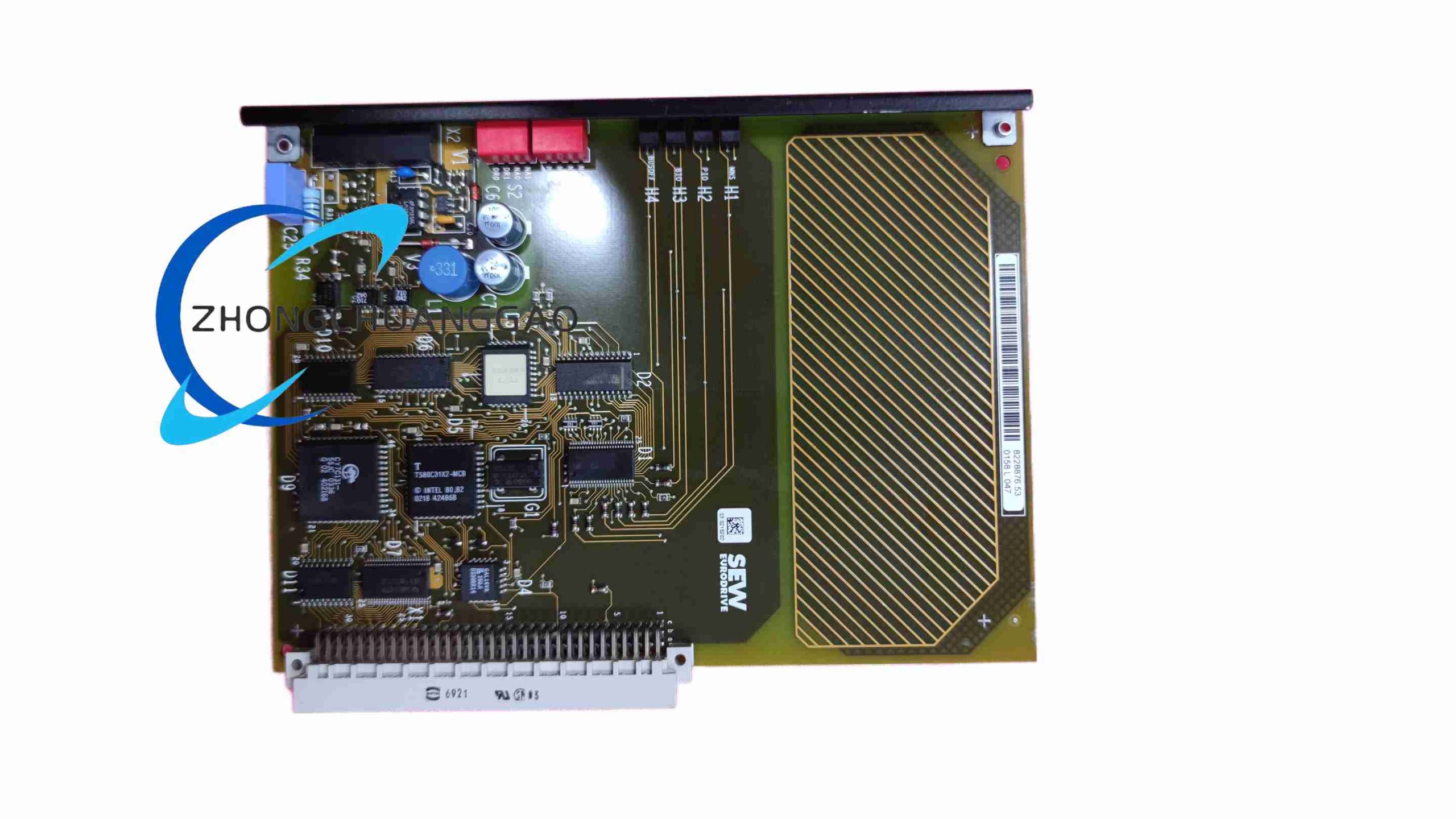
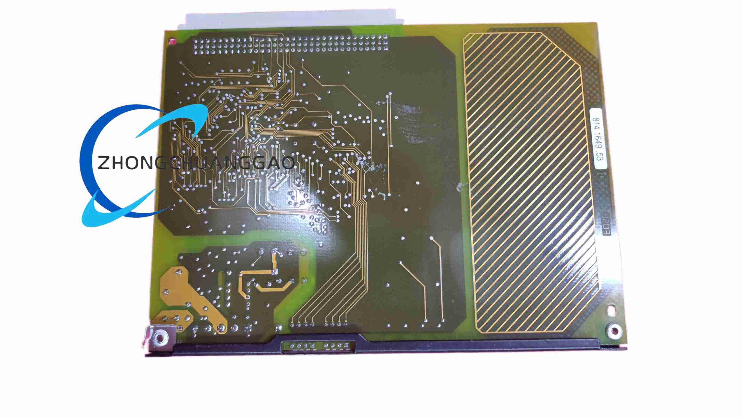
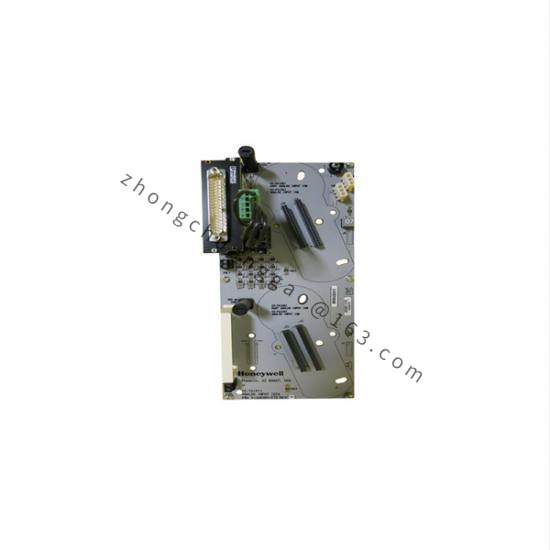
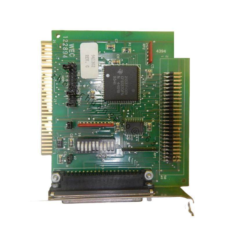
Industrial drive main board architecture. Surface-mount component layout. Operating temperature is 0 to 50 degrees Celsius in standard control-panel installations. Storage temperature is minus 25 to plus 70 degrees Celsius. Relative humidity is 5 to 95 percent non-condensing.
Functional Features
Motor control processing, torque and speed regulation, fault diagnostics, fieldbus communication support, parameter storage and replacement identification through SEW part marking.
Application Scenarios
Used in conveyor systems, pump and fan drives, material handling, machine tools and general industrial motion control where SEW inverter platforms are deployed.
Performance Parameters
Board operation depends on the matched inverter power rating, motor type and firmware profile. Diagnostic LEDs and communication status indicate processor boot, bus handshake and fault conditions during service.
Material Composition
Multilayer PCB, high-density surface-mount components, power driver interfaces, microprocessor or DSP devices, connector assemblies and environmental conformal coating.
Structural Characteristics
Internal chassis-mounted controller card with alignment pins, multi-pin power and signal connectors, firmware memory and diagnostic indicators. Exact mechanical layout depends on the inverter series.
Working Principle
The main board receives setpoint commands, feedback signals and fieldbus data, calculates PWM or switching profiles, and directs power-stage modules to regulate motor voltage and frequency. Closed-loop feedback maintains speed, torque and position accuracy.
Installation Requirements
Disconnect and lock out inverter power. Verify DC-bus capacitors are fully discharged with a calibrated meter. Use alignment pins and specified connectors. Reload or verify drive parameters from backup after installation.
Usage Precautions
Always follow ESD handling procedures. Never work on the board with energized bus capacitors. Confirm firmware and motor parameter sets before run-up. Inspect connector pins, thermal interfaces and conformal coating during preventive maintenance.