Technical Specifications
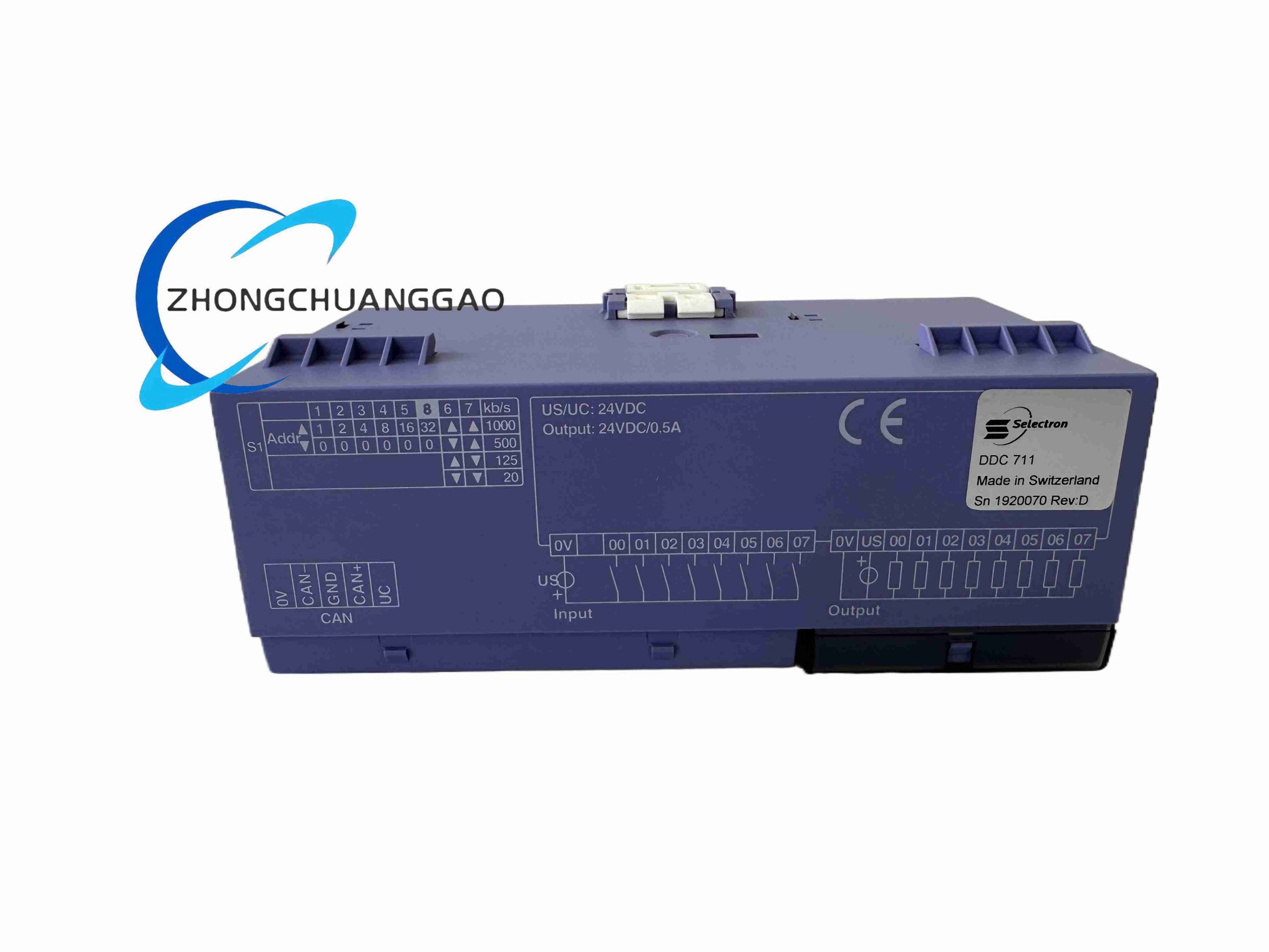
Supply voltage: 24 VDC, 24 VDC ±10%.
Maximum power consumption: 6 W.
Local bus: Selectron Selebus backplane for stacked I/O modules.
External communication: RS485 Modbus RTU.
Maximum local I/O modules: 8 expansion modules per DDC711.
Logic scan cycle: 1 ms minimum according to configuration.
Baud rate: up to 19.2 kbps for external Modbus interface according to configuration.
Functional Features
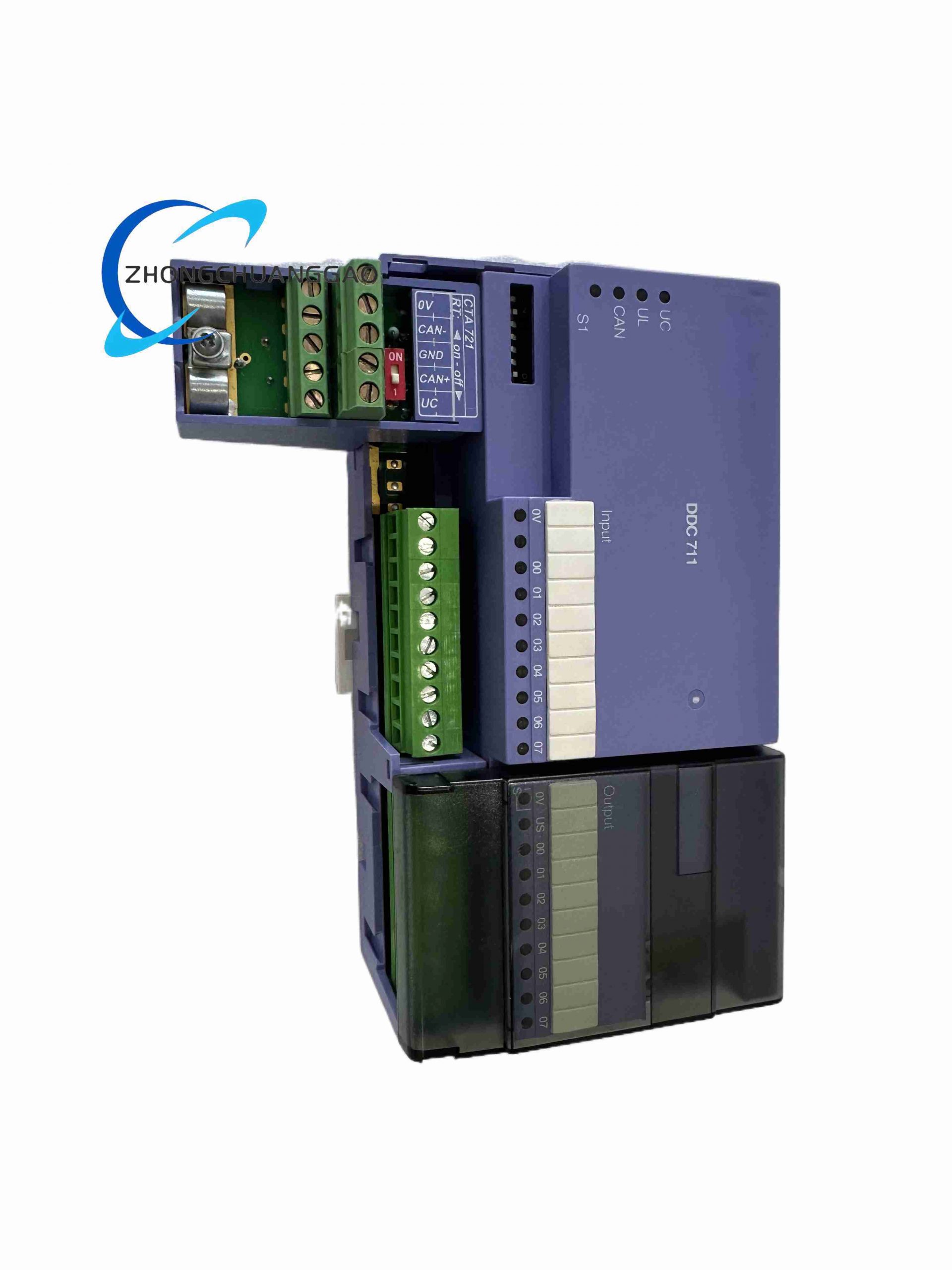
Couples local digital I/O slices with upper control system.
Executes preconfigured distributed logic and interlocks.
Provides Modbus RTU interface for third-party controllers.
Supports local I/O expansion without excessive external wiring.
Gives front LED status for power, run and bus faults.
Performance Parameters
Operating temperature: -20°C to +70°C.
Humidity: 5% to 95% non-condensing.
Protection class: IP20 for indoor cabinet installation.
Communication diagnostics through front LED indicators.
Material Composition
Housing: self-extinguishing PA66 engineering plastic.
PCB: industrial FR4 with gold-plated bus connectors.
Isolation: signal isolation transformers or optoisolators according to circuit section.
Terminals: spring-cage nickel-plated copper terminals.
Structural Features
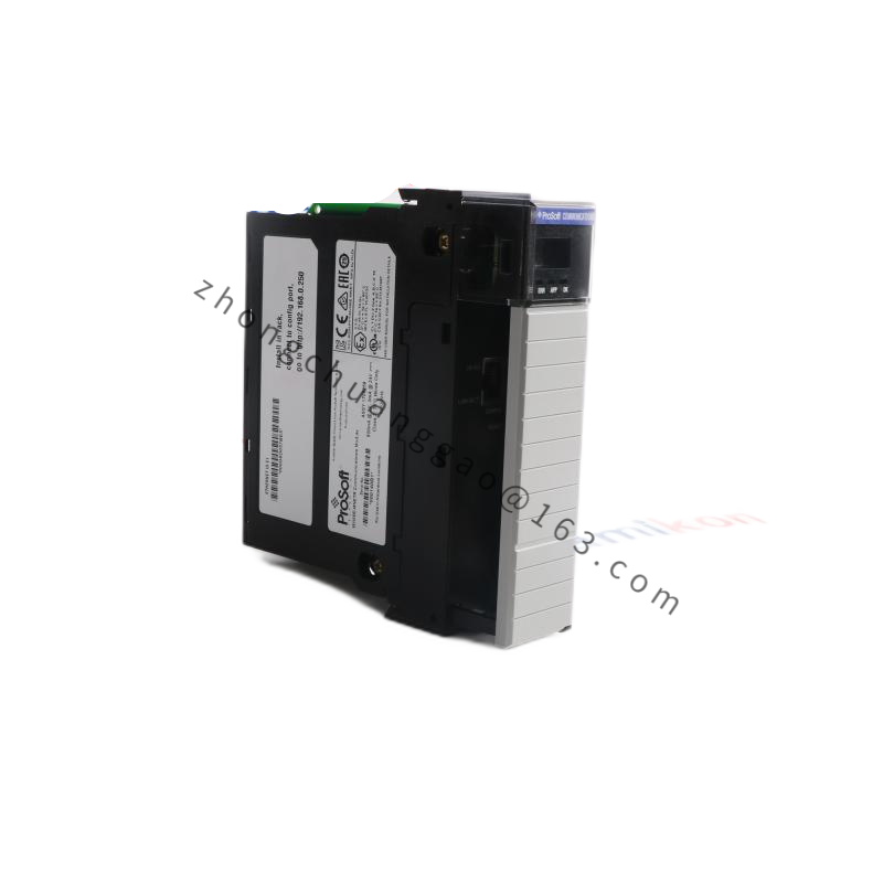
DIN-rail modular housing.
Left side Selebus backplane connector for local I/O stacking.
Right side RS485 and 24 VDC terminals.
Front LEDs for power, run and communication fault.
Working Principle
The coupler receives commands from the master controller through Modbus RTU or higher-level network. It distributes instructions to local I/O modules over the Selebus backplane, collects digital input status, executes configured logic and returns processed data to the master system. Local logic can continue predefined operations during communication interruption according to stored configuration.
Installation Requirements
Mount on 35 mm DIN rail inside an IP20 or higher control cabinet.
Use shielded twisted pair for RS485 Modbus communication.
Install 120 Ω termination at both physical ends of the Modbus bus.
Separate 24 VDC power cables from communication cables.
Lock stacked I/O modules mechanically to ensure backplane contact.
Usage Precautions
Do not connect more than 8 local I/O expansion modules per DDC711.
Disconnect 24 VDC before adding or removing stacked modules.
Verify Modbus address, baud rate and termination before commissioning.
Keep ambient temperature within -20°C to +70°C.
Inspect shield grounding periodically to prevent bus communication errors.