Technical Specifications
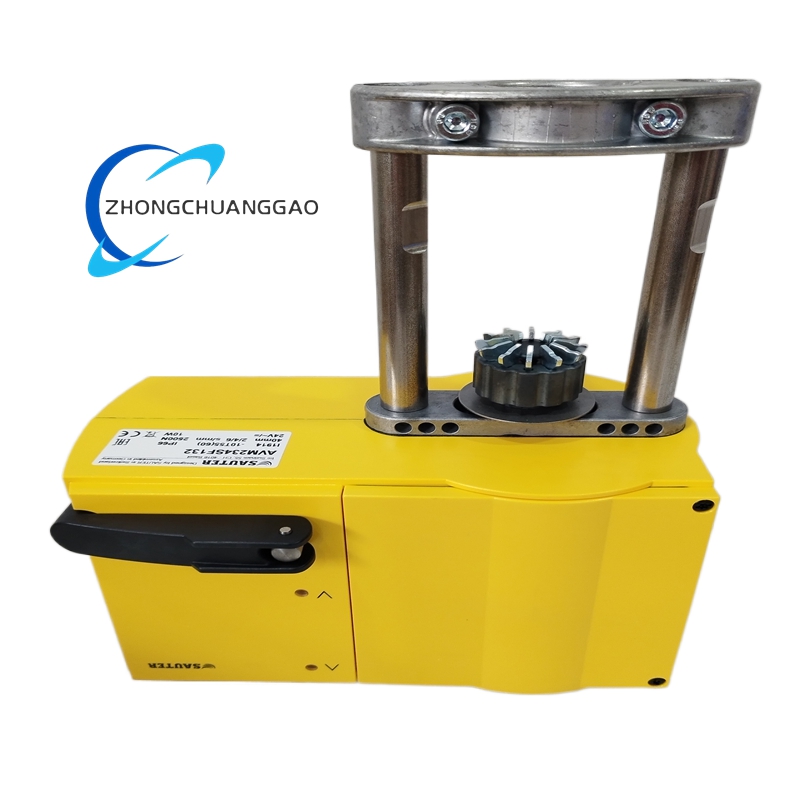
- Force: 2500 N
- Power supply: 24 V AC/DC
- Stroke: up to 49 mm; minimum valve stroke 8 mm
- Positioning time: 2/4/6 s per mm selectable
- Control signals: 0–10 V, 4–20 mA, 2-point, 3-point
- Compatible valves: Sauter VQD/BQD, VQE/BQE, VUG/BUG, VUS/BUS, VUP, V6R/B6R and selected partner valves
- Characteristics: linear, quadratic, equal-percentage selectable by coding switch
- Spindle connection: automatic coupling after control voltage application
- Electrical connection: screw terminals up to 2.5 mm²
- Cable entries: three pre-scored entries, M20x1.5 x2 and M16x1.5 x1
- Mounting orientation: vertical upright to horizontal; not suspended/inverted per installer guidance
- Diagnostics: two status LEDs, signal-type auto-detection
Functional Features
Automatic valve stroke detection, electronic force-limited cutoff, non-volatile position memory, analog or switching control, characteristic selection, LED commissioning feedback, reduced operating noise.
Application Scenarios
District heating substations, air-handling-unit chilled/heating valves, process control loops, retrofit of Sauter VQD/BQD valve bodies, building management modulation.
Material Composition
Alloy/light-metal valve coupling components, engineered plastic/metal electronics housing, stepping motor, screw spindle, screw terminals.
Structural Characteristics
Linear actuator body with spindle adapter, coding switches, LED window, cable glands, DIN/valve-mounting flange interface.
Working Principle
After applying 24 V, the controller detects 0–10 V, 4–20 mA or switching command, drives the stepping motor to the commanded position, measures spindle force and stroke, performs automatic cutoff at end limits, and stores calibrated stroke data for subsequent modulation.
Installation Requirements
Mount in vertical-to-horizontal orientation only. Use approved Sauter valve adapter. Tighten spindle coupling as instructed; automatic connection occurs after energization. Set running time and characteristic coding switches before commissioning. Use M20/M16 cable glands with proper sealing.
Usage Precautions
Do not mount suspended/inverted to avoid condensation into motor housing. Do not interrupt automatic initialization. Confirm 24 V AC/DC only; use separate Sauter AC/DC module for 230 V applications. Match control signal type with controller output and coding configuration.