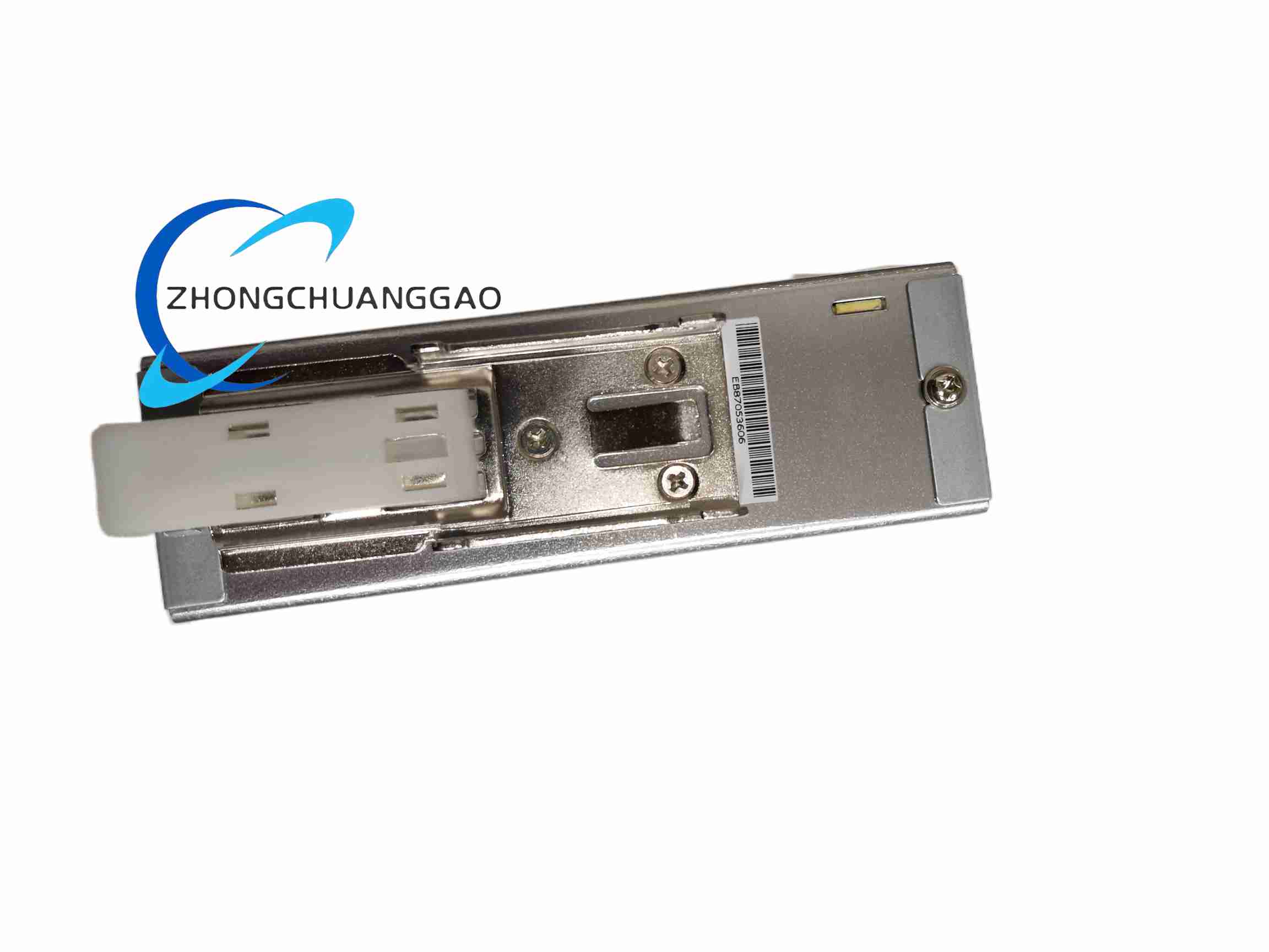
Technical Specifications
Channels: 8 analog channels.
Signal types: 0–10 V and 4–20 mA typical; individual channels may be input, output or mixed according to the variant.
Resolution: 12-bit to 16-bit class according to Parker analog module grade.
Power supply: 24 V DC nominal, ±20% typical.
Communication: local expansion bus to compatible Parker controller; external fieldbus handled by host controller.
Mounting: 35 mm DIN rail.
Dimensions: compact DIN-rail enclosure; expect a larger body or double-row terminals than the 4-channel version, but use the 14293 drawing for exact size.
Protection: IP20 in-cabinet.
Operating temperature: 0 to +55 °C typical.
Humidity: 5–95% RH non-condensing.
Compliance: CE and RoHS typical for Parker automation modules.
Functional Features
Expands analog signal capacity for larger process or machine systems without adding a separate gateway.
Supports voltage and current transducers such as thermotransmitters, pressure sensors, flow meters, load cells with signal conditioners, position potentiometers and analog valve commands.
Pluggable terminals enable fast channel replacement and reduced wiring downtime.
Software range selection and scaling where the firmware permits.
Diagnostic LEDs provide power, bus and fault indication according to the controller system.
Application Scenarios
Multi-loop process skids with several temperature, pressure and flow points.
Converting, printing and laminating lines with multiple tension, nip and web-position sensors.
Hydraulic presses and proportional systems requiring several command and feedback analog channels.
Test laboratories and calibration rigs with simultaneous multi-sensor acquisition.
Factory automation lines already controlled by Parker PAC or compatible controller platforms.
Performance Parameters
Per-channel accuracy depends on selected range, resolution, temperature drift and transducer class.
Total scan performance depends on channel count, controller task period and bus loading.
Electrical isolation, channel-to-channel crosstalk and EMC immunity must be confirmed from the 14293 detailed specification.
Expected industrial MTBF follows Parker environmental testing for DIN-rail analog modules.
Material Composition
Housing: industrial DIN-rail enclosure with marked channel sections.
Terminals: plated contact elements in flame-retardant connector body.
PCB: industrial signal-conditioning board with SMD components.
Shielding elements: internal ground separation between field-side and logic-side circuits according to the isolation grade.
Structural Characteristics
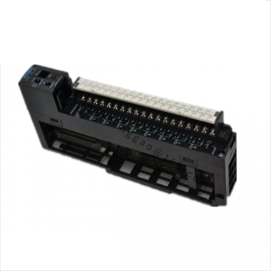
Eight-channel layout with grouped terminals for input/output, power and expansion bus.
LED indicators for system power, communication and fault status.
Local expansion interface for direct mounting or bus coupling to the Parker host controller.
Cable strain relief and labeling space for loop identifiers and calibration tags.
Working Principle
Field analog voltages or currents are conditioned per channel, converted by ADCs in input configuration or generated by DACs and output drivers in output configuration. The module exchanges digital process data with the Parker controller through the local expansion bus. The controller executes scaling, alarming, PID regulation and data recording, then issues analog commands or uses acquired values for supervisory control.
Installation Requirements
Install on 35 mm DIN rail in a grounded, ventilated cabinet.
Provide 24 V DC with correct fusing and observe total module power consumption for all eight channels.
Use individually shielded twisted pairs for each critical analog loop.
Separate analog wiring from Variable Frequency Drive output, contactor coils and high-current conductors.
Configure channel types, ranges and controller addresses before applying process signals.