Technical Specifications
Channels: 4 analog channels.
Signal types: 0–10 V and 4–20 mA typical; verify each channel as input or output from the variant label.
Resolution: 12-bit to 16-bit class according to Parker analog module grade.
Power supply: 24 V DC nominal, ±20% typical for cabinet automation modules.
Communication: local expansion bus to compatible Parker PAC/controller; higher-level fieldbus is handled by the host controller.
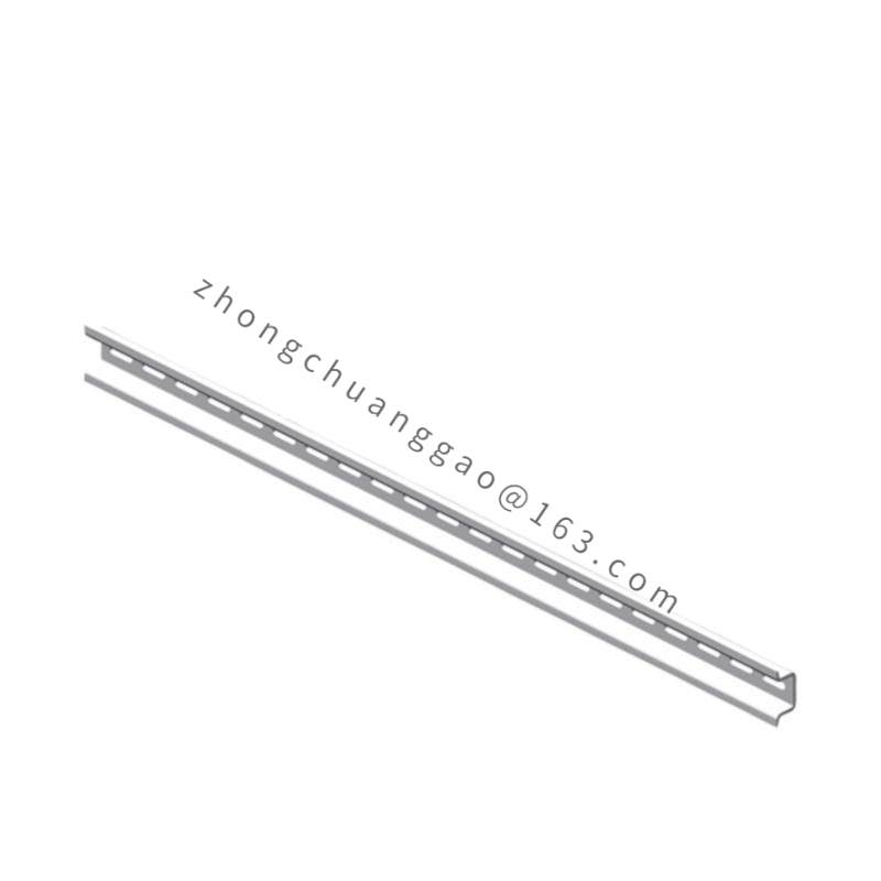
Mounting: 35 mm DIN rail in control cabinet.
Dimensions: approximately 110×70×60 mm typical for compact DIN-rail analog modules; confirm against the specific 13574 drawing.
Weight: approximately 0.25 kg typical.
Protection: IP20 in-cabinet.
Operating temperature: 0 to +55 °C typical cabinet environment.
Humidity: 5–95% RH non-condensing.
Compliance: CE and RoHS typical for Parker control modules.
Functional Features
Brings field analog signals such as pressure, temperature, level, flow, tension or position feedback into the Parker control system.
Supports software-selectable voltage/current ranges where the firmware and wiring allow.
Provides pluggable terminals for fast maintenance and channel rewiring.
Works with shielded analog cabling and proper instrument grounding to reduce noise.
Stores configuration through the host controller project; channel scaling is performed in the controller application.
Application Scenarios
Process skids with temperature, pressure and flow transmitters.
Packaging and converting machines requiring web tension or dancer position feedback.
Hydraulic and pneumatic systems with proportional valve command or pump pressure monitoring.
Test stands and R&D rigs needing flexible 4-channel analog signal capture.
General machine automation where a Parker controller already manages logic and fieldbus communication.
Performance Parameters
Accuracy depends on range, resolution, temperature drift and external transmitter quality.
Sampling rate follows the host controller task cycle and module scan configuration.
Noise immunity improves with twisted-pair shielded cable, separated tray routing and single-point shield grounding.
MTBF and calibration interval must be taken from the specific Parker CPAR-04AE release documentation.
Material Composition
Housing: industrial molded enclosure for DIN-rail mounting.
Terminals: nickel-plated contact elements in flame-retardant terminal carrier.
PCB: industrial-grade board with SMD signal-conditioning components.
Labeling: engraved or printed channel markers and variant barcode according to Parker packaging.
Structural Characteristics
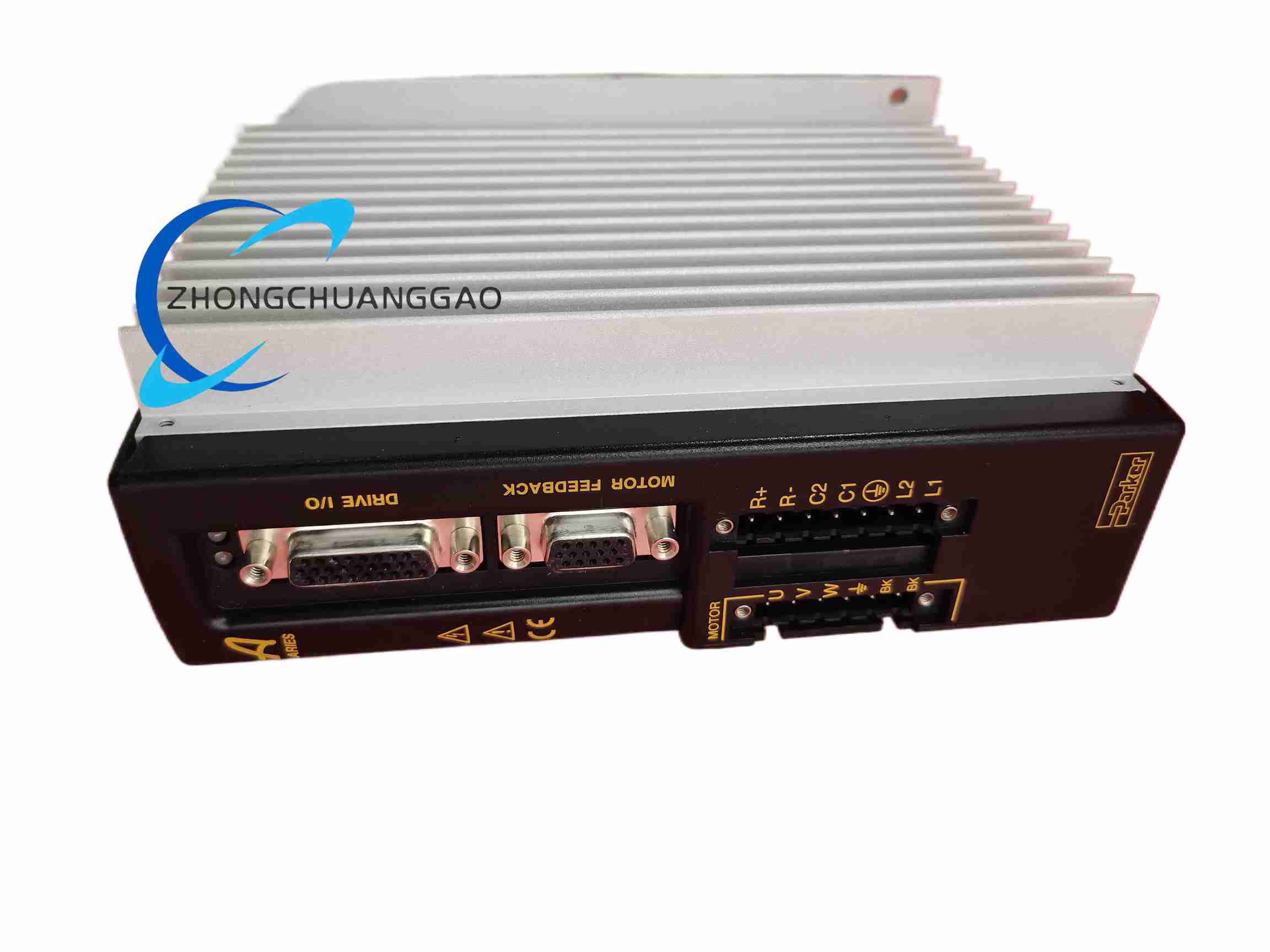
Compact DIN-rail body with front channel terminals or pluggable connector block.
Status LEDs for power, communication and per-channel faults according to the firmware.
Local expansion connector for direct attachment to the compatible Parker controller backplane or bus coupler.
Separate field wiring area from internal logic to simplify troubleshooting.
Working Principle
Each analog channel conditions the field transducer signal through filtering, amplification and ADC conversion for input modules, or through DAC and output drivers for output modules. The module transfers converted data to the Parker host controller over the local expansion interface. The controller executes scaling, alarming, PID loops or data logging, then returns analog output values or uses the data for closed-loop process control.
Installation Requirements
Mount on 35 mm DIN rail inside a ventilated control cabinet.
Supply clean 24 V DC with proper fusing and observe polarity on power terminals.
Use twisted-pair shielded cable for 4–20 mA and 0–10 V signals.
Connect sensor/composer commons to the instrument ground defined by the controller manual.
Match the module orientation and expansion address to the host controller project before power-up.
Usage Precautions
De-energize the cabinet before wiring or replacing the module.
Verify 2-wire transmitter loop power requirements before connecting current inputs.
Do not exceed 10 V or 20 mA signal limits unless the variant explicitly supports extended range.
Perform periodic calibration check with a reference source.
Replace with the identical CPAR-04AE-13574 variant and restore the controller project parameters after swap.