Technical Specifications
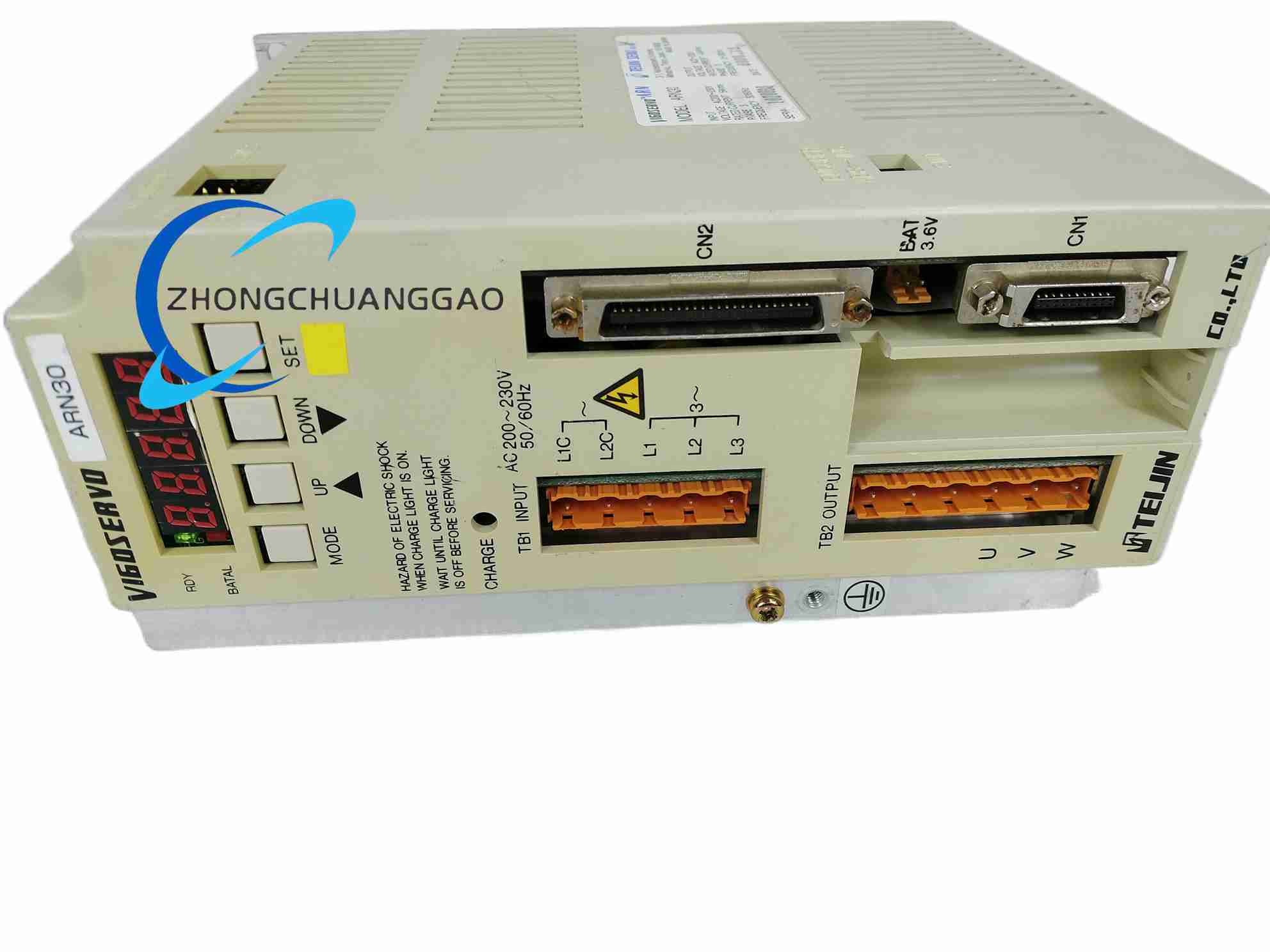
Contact Form: 1 Form C, reversed-contact ARN30 variants available alongside standard ARN10 where listed.
Impedance: 50 ohm.
Frequency: up to 8 GHz; continuous high-frequency characterization is commonly specified to 6 GHz with reference data beyond that.
Carrying Power: up to 150 W CW at 2 GHz with heat sink, lower without heat sink.
Coil Voltage: 4.5 V, 12 V or 24 V DC according to ARN30A4H, ARN30A12, ARN30A24 and equivalents.
Coil Power: approximately 320 mW.
Insertion Loss: 0.1 dB to 1 GHz, 0.12 dB to 2 GHz, 0.15 dB to 3 GHz, increasing at higher bands.
Isolation: 60 dB to 1 GHz, 55 dB to 2 GHz, 45 dB to 3 GHz, 30 dB to 6 GHz.
VSWR: 1.1 or less to 1 GHz, 1.15 to 2 GHz, 1.2 to 3 GHz, 1.3 to 6 GHz.
Dielectric Strength: 500 Vrms for 1 minute between open contacts and between contact/coil according to rating conditions.
Operating Temperature: -40 to +85°C.
Package: SMD, approximately 9.6 × 14.6 × 10.0 mm.
Functional Features
Gold-plated contacts for stable RF performance.
Miniature SMD construction for high-density RF boards.
Single-side-stable and selected latching options within the RN family.
RoHS-compliant construction according to Panasonic RN data.
Application Scenarios
Base-station transmitter switching.
Wireless device RF front-end switching.
Spectrum analyzers, oscilloscopes and microwave test sets.
High-frequency amplifier path selection.
Material and Structure
Layered RF ceramic/plastic SMD package.
Gold contact materials and sealed armature construction according to flux-resistant or sealed variant.
Surface-mount coil and RF terminals.
Working Principle
The DC coil energizes an electromagnetic armature that moves the RF contact set. The RF signal path is switched between common and normally open/closed contacts with matched 50 ohm geometry, while the coil circuit remains isolated from the RF contacts.
Installation Requirements
Use 50 ohm controlled-impedance PCB traces and grounding vias.
Provide heat sinking for high-power 2 GHz operation.
Follow reflow profile and tape-reel orientation specified by Panasonic.
Match coil voltage to ARN30A4H, ARN30A12 or ARN30A24 variant.
Usage Precautions
Do not exceed rated carrying power without heat-sink verification.
Verify insertion loss and isolation at the actual operating frequency.
Avoid condensation, corrosive atmosphere and mechanical stress on SMD terminals.
For low-level RF or fast-switching life tests, request application guidance from the manufacturer.