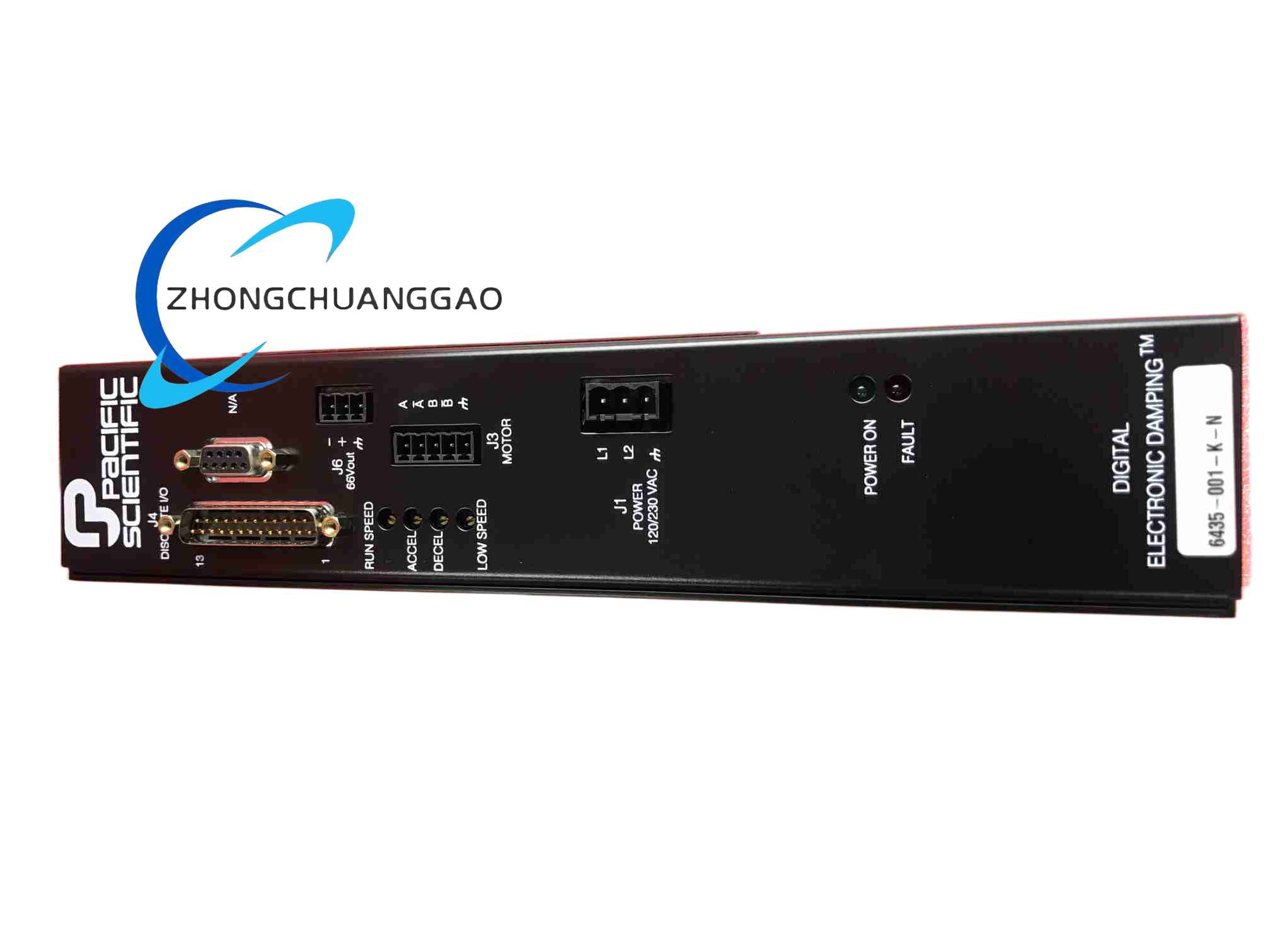
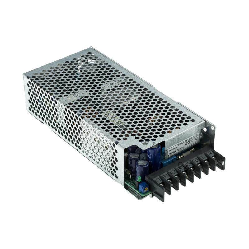
Technical Specifications: AC input is 120/240 VAC, 50/60 Hz, switch selectable. Internal DC output is 66 VDC with total internal and auxiliary power near 300 W. Motor current is adjustable from 0.625 A rms to 5.0 A rms. Chopper frequency is approximately 20 kHz bipolar PWM. Operating temperature is 0°C to 50°C.
Functional Features: Microstep resolution includes full, 1/2, 1/5, 1/10, 1/25, 1/50, 1/125 and 1/250 steps. Digital electronic damping reduces mid-speed resonance. Optical isolation is provided for step, direction, run/stop, enable and low-speed inputs. Adjustable acceleration and deceleration ramps are set by onboard potentiometers.
Application Scenarios: X-Y tables, slides, packaging machinery, labeling machines, robotics, index feeders, semiconductor handling, CNC auxiliary axes and specialty automation equipment.
Performance Parameters: Auxiliary 66 VDC output supports additional drives through the designated connector. Idle current reduction lowers motor heating during dwell periods. Short-circuit, overvoltage and overtemperature protection disable the output until power reset.
Material Composition: Steel or aluminum drive enclosure, printed circuit boards, MOSFET power devices, transformer/SMPS components, potentiometers, DIP switches, optical isolators and cooling elements.
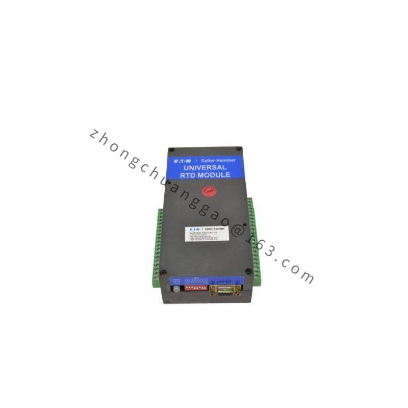
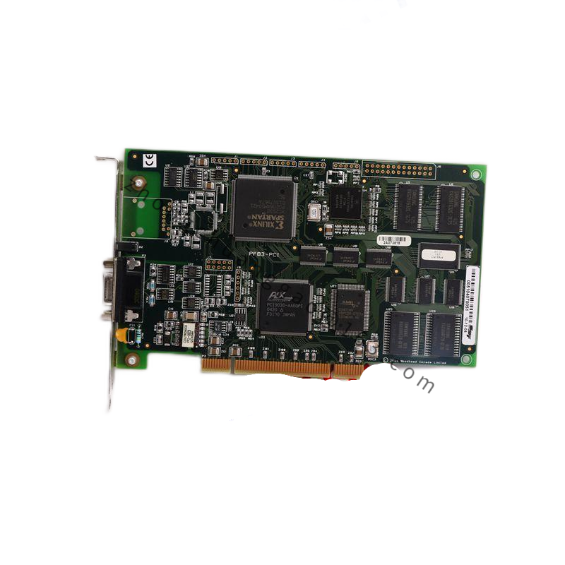
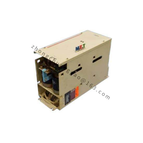
Structural Characteristics: Combined power supply, oscillator card and drive card assembly with AC input section, motor output terminals, control input connectors and adjustment components.
Working Principle: The AC input is rectified and regulated to a DC bus. The oscillator creates step pulses and direction signals. The chopper drive converts these commands into precisely controlled stepper winding currents. Electronic damping compensates resonance to maintain torque and positioning accuracy.
Installation Requirements: Select 120 V or 240 V AC input by the onboard switch before energizing. Mount in a ventilated panel with clearance for heat dissipation. Connect motor phases according to the drive manual. Use shielded control cables for step and direction signals where required.
Usage Precautions: Confirm motor current rating before DIP switch setting. Do not touch output terminals while AC power is applied. Reset power after a fault condition. Avoid moisture, excess dust and ambient temperature above 50°C.