Technical Specifications
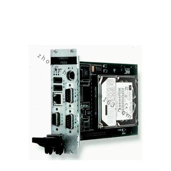
Bus architecture is VMEbus compliant with IEEE-1014. Primary function is system communication and signal routing. Data lines use opto-isolation to protect core logic. Form factor is standard VME double Eurocard. Operating environment is 15 to 30 degrees Celsius, non-condensing cleanroom rack ambient.
Functional Features
High-speed bus transceivers, multi-channel opto-isolation, front-edge status LEDs for power and communication, configuration jumpers or address settings, and deterministic packet or signal handling.
Application Scenarios
Used for chamber automation communication, subassembly handshaking, controller data routing and legacy tool modernization support on plasma etch or deposition platforms.
Performance Parameters
Powered from standard VME chassis DC backplane rails. Communication diagnostics include power LED, heartbeat LED and bus traffic indicators. Boards are qualified through channel cycling, timing verification and thermal run-in by service suppliers.
Material Composition
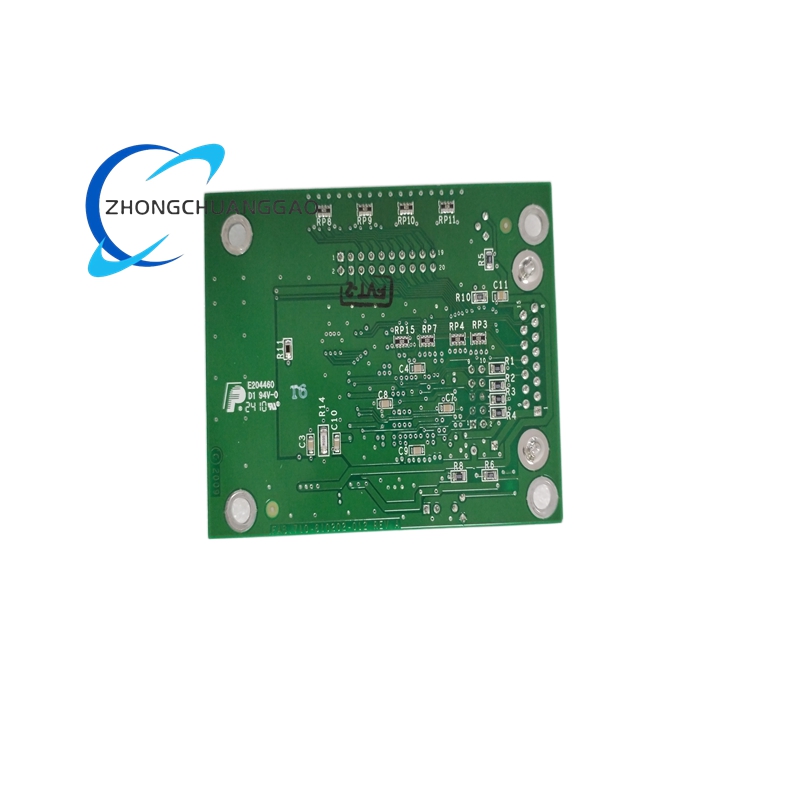
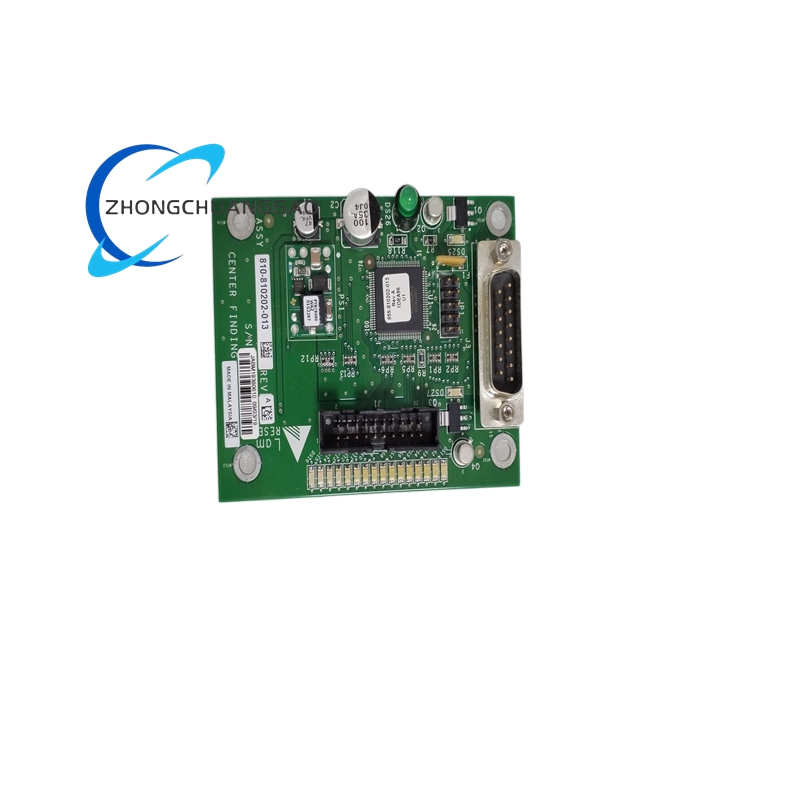
Multilayer PCB, transceiver ICs, optocouplers, microcontroller or logic devices, VME edge connector with controlled-finish contacts, and conformal coating where specified.
Structural Characteristics
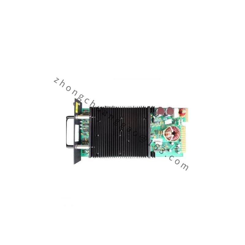
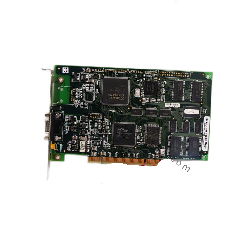
Double Eurocard plug-in design with backplane connector, address or jumper blocks, diagnostic LEDs and guided card-cage mounting hardware.
Working Principle
The board receives communication frames from the VME controller, converts and isolates signals as required, and routes data to target subsystems. Return status is formatted and placed on the backplane for the main controller.
Installation Requirements
Shut down and de-energize the VME chassis. Replicate address switches and jumpers from the original board. Align the card carefully with backplane guides and seat fully. Verify communication LEDs after power-on.
Usage Precautions
Do not hot-swap the module. Incorrect address or jumper settings can cause bus contention and boot failure. Inspect pins and connector alignment before insertion. Store and handle in ESD-safe packaging.