Technical Specifications
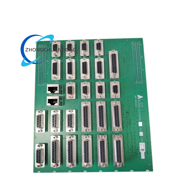
Bus architecture is VMEbus compliant with IEEE-1014. Channel density is 32 digital I/O channels. Isolation uses optocouplers to protect internal logic. Hardware addressing uses hexadecimal switches or jumper blocks. Form factor is standard VME double Eurocard.
Functional Features
Optical isolation per channel, status LED array for channel and bus activity, deterministic interlock polling, high-noise rejection and secure backplane communication.
Application Scenarios
Used for chamber door interlocks, vacuum and gas panel safety signals, robot cell status, and process tool automation on legacy VME etch or deposition platforms.
Performance Parameters
Operating ambient is 15 to 30 degrees Celsius in cleanroom rack enclosures. Channels are tested for threshold switching, isolation integrity and continuous state monitoring during qualification.
Material Composition
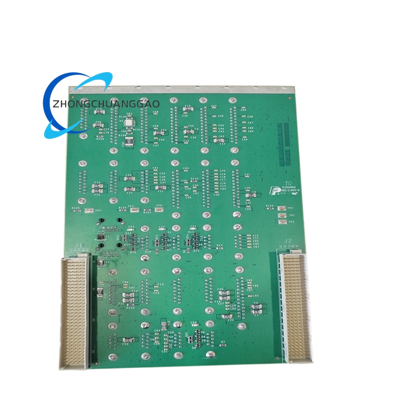
Multilayer FR4 PCB, optocouplers, digital driver ICs, gold or controlled-finish VME edge connector, and industrial conformal coating where specified.
Structural Characteristics
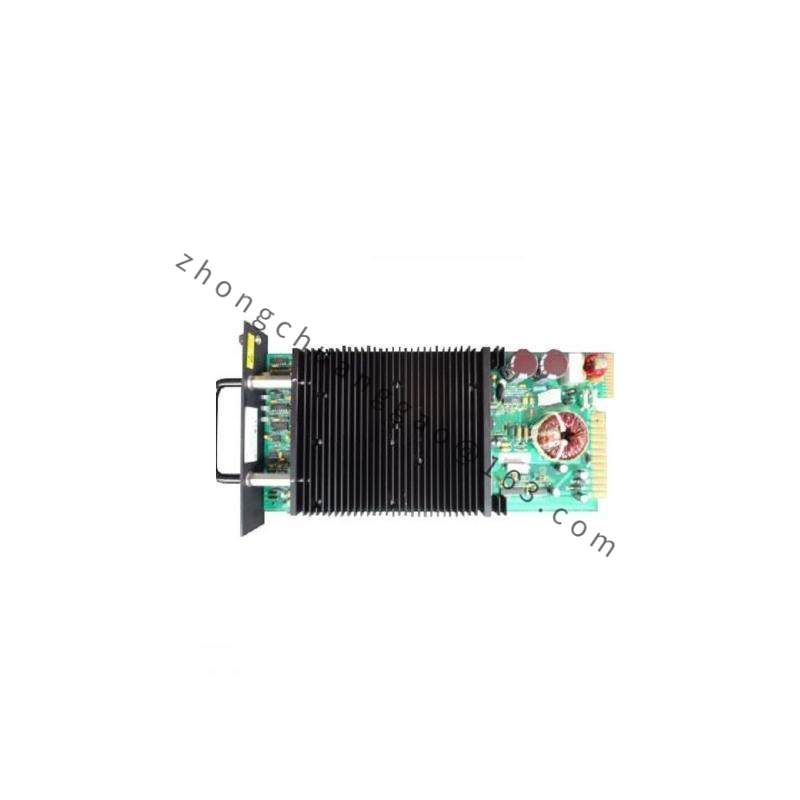
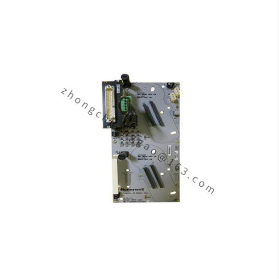
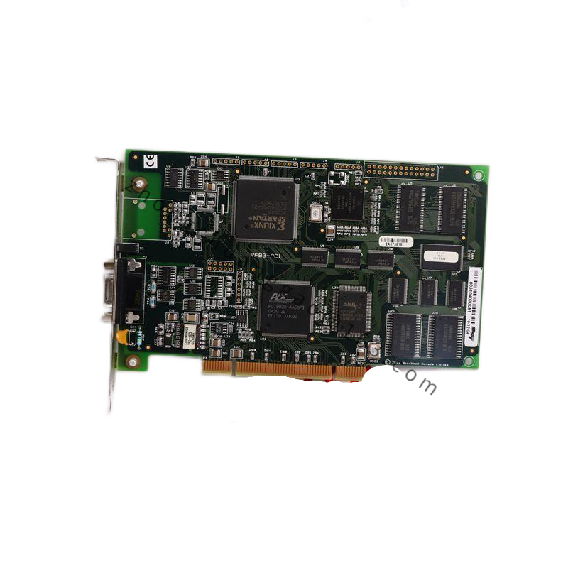
Double Eurocard PCB with VME P1 and P2 style interface, hex address switches, jumper blocks, LED indicators and terminal or header access for field wiring.
Working Principle
External sensors and interlock contacts feed opto-isolated inputs. The VME controller reads channel states, executes logic according to tool software, and returns output commands through isolated drivers to actuators or alarm devices.
Installation Requirements
Power down the VME rack completely. Copy hex address and jumper settings from the failed board. Align the card with backplane guides and insert without rocking. Verify terminal mapping before applying field voltage.
Usage Precautions
Never hot-plug the board in an energized rack. Do not connect high-voltage field lines directly to low-voltage sense pins without proper relay isolation. Use ESD grounding. Check LED status to separate sensor faults from board faults before replacement.