Technical Specifications
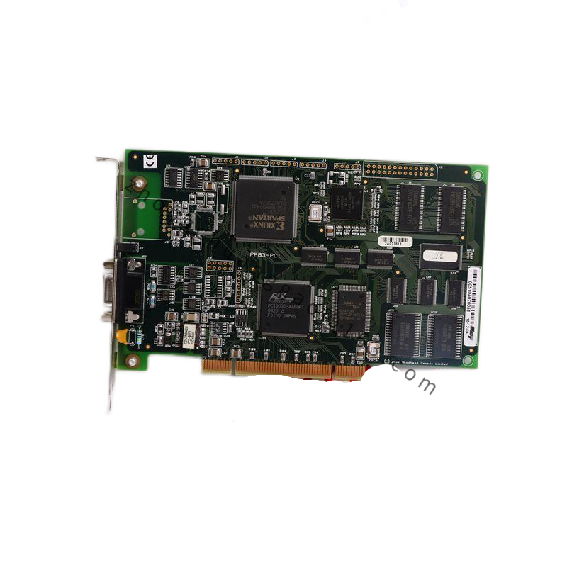
Serial I/O configuration provides six independent RS-232 or RS-422 channels with UART FIFO buffering up to 256 bytes per port, baud rates from 300 to 115200, hardware flow control and 5 or 12 volt backplane supply. RF interface listings state 13.56 MHz operation, 2500 to 3000 watts continuous-wave capacity, 50 ohm nominal input and output, and RS-485 or Ethernet diagnostics. General I/O controller version uses opto-isolated digital lines, high-speed bus transceivers and an onboard microcontroller with flash firmware.
Functional Features
Deterministic signal routing, opto-isolation, FIFO buffering, flow control, reflection and forward-power monitoring, capacitor-position feedback, fault logging and SECS or GEM host communication in supported builds.
Application Scenarios
Used in NAND and DRAM etch, high-aspect-ratio contact and trench etch, TSV and MEMS deep silicon etch, and general chamber automation. Serial version connects mass flow controllers, robots and endpoint sensors. RF version supports bias and source power stability.
Performance Parameters
Serial channels support up to 115200 baud with parity and flow-control configuration. RF listings state full-range match response under 100 milliseconds and reflected power management for plasma stability. Controller version operates in cleanroom chassis ambient of 15 to 30 degrees Celsius.
Material Composition
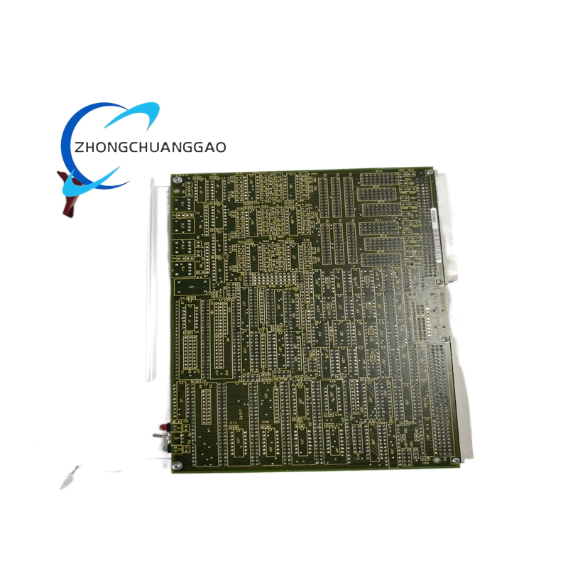
Multilayer PCB, surface-mount integrated circuits, optocouplers, UART transceivers or RF capacitors and inductors, gold or controlled finish connectors, and industrial conformal coating.
Structural Characteristics
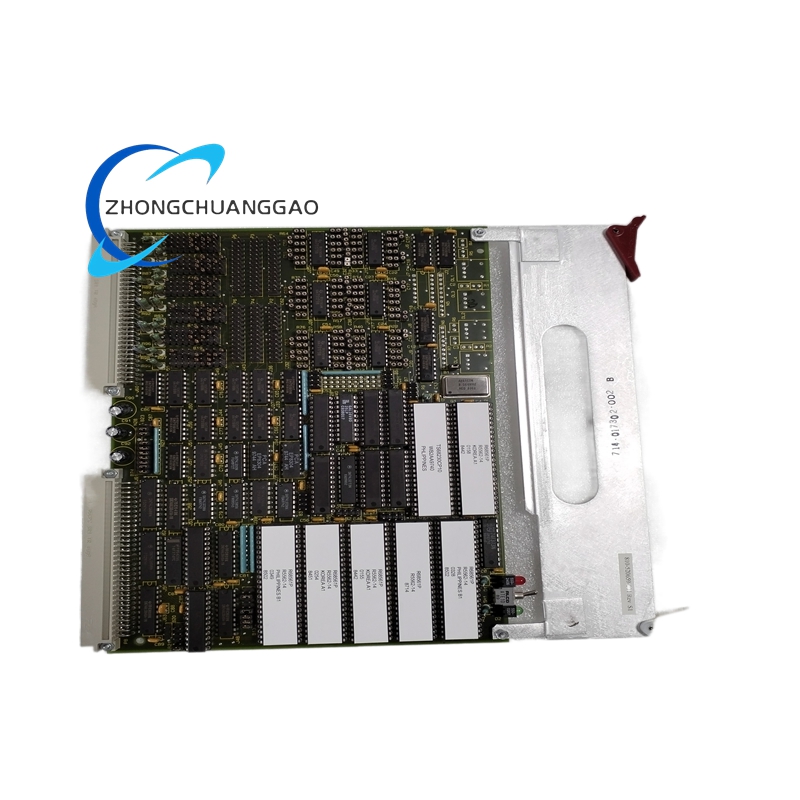
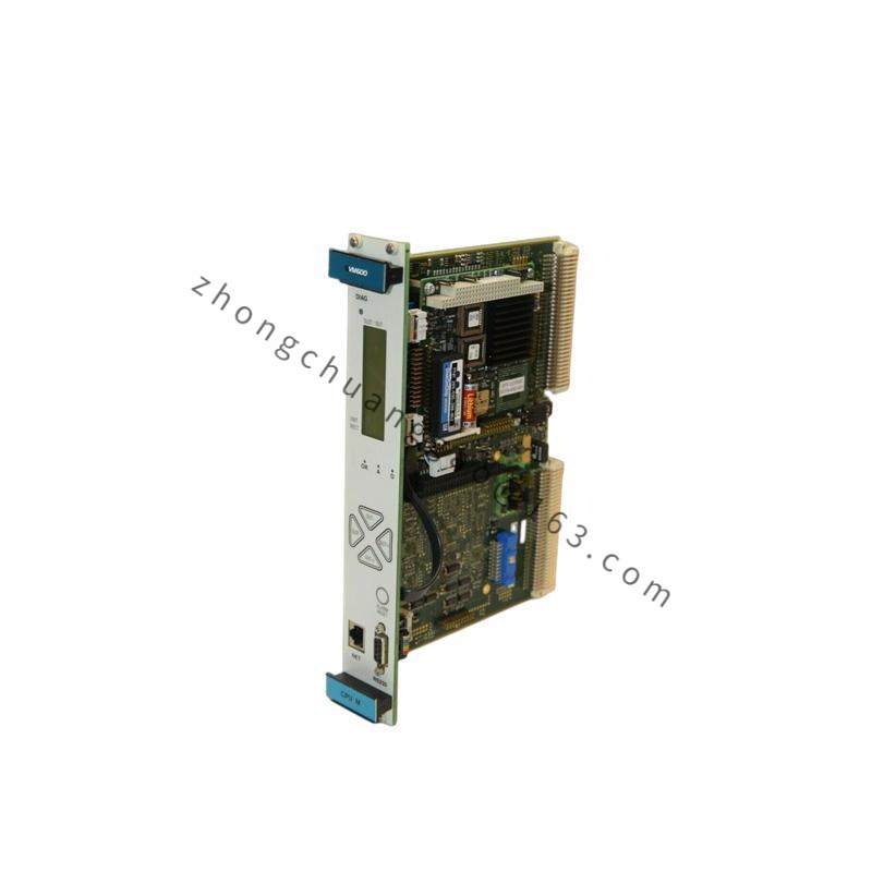
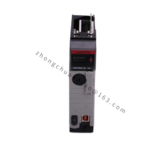
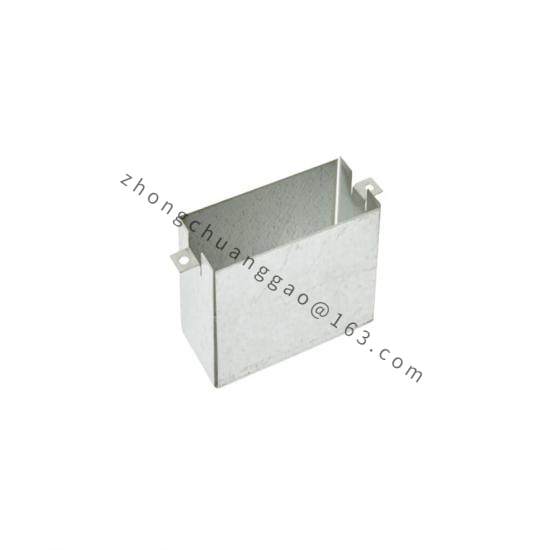
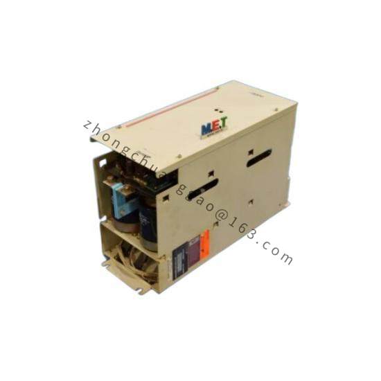
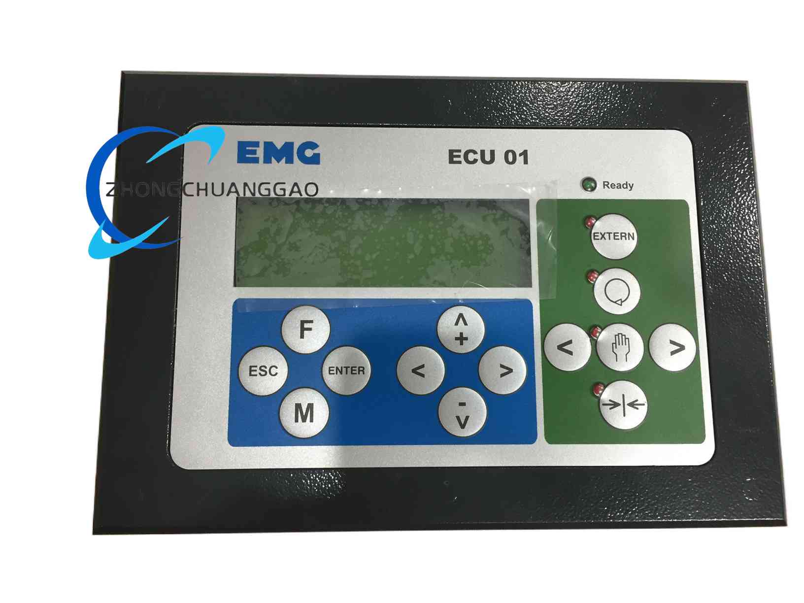
Proprietary card-cage PCB for I/O and serial versions. RF version uses enclosed match housing with tunable elements, sensors, cooling interface and communication port. All versions include status LEDs for power, communication and fault indication.
Working Principle
Serial version conditions asynchronous ports, buffers data and transfers framed messages to the system CPU over the backplane. I/O controller version executes digital command routing and isolation. RF version measures forward and reflected power, adjusts matching elements and reports tuner position and fault states to the host.
Installation Requirements
Identify the exact hardware variant and tool software revision before replacement. Copy address switches, jumpers and firmware parameters from the removed unit. Power down the rack and discharge static potential. Seat the card squarely in the assigned slot and verify communication after power-on.
Usage Precautions
Do not hot-swap the module. Verify firmware compatibility to avoid bus contention or communication timeouts. Use ESD grounding for all handling. For RF versions, confirm cooling connection, 50 ohm cabling and reflected-power alarms before process start.