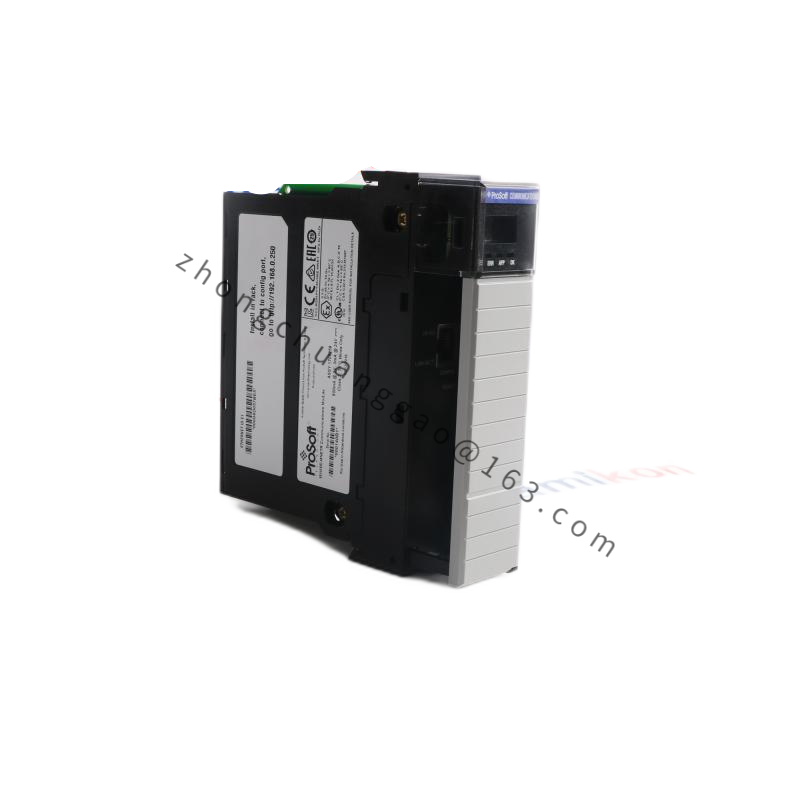
Technical Specifications
Compatible platforms include Exelan, Kiyo and Vector etch systems for the multiplexer configuration. Certain supplier listings describe RF match use with operating frequencies of 2 MHz, 13.56 MHz, 27 MHz or 60 MHz. Power capacity in match configuration is rated up to 2000 to 5000 watts depending on system build. Impedance matching range is 0.5 to 500 ohms in match listings. Backplane power rails for the multiplexer version include +24 V, +5 V and plus or minus 15 V DC.
Functional Features
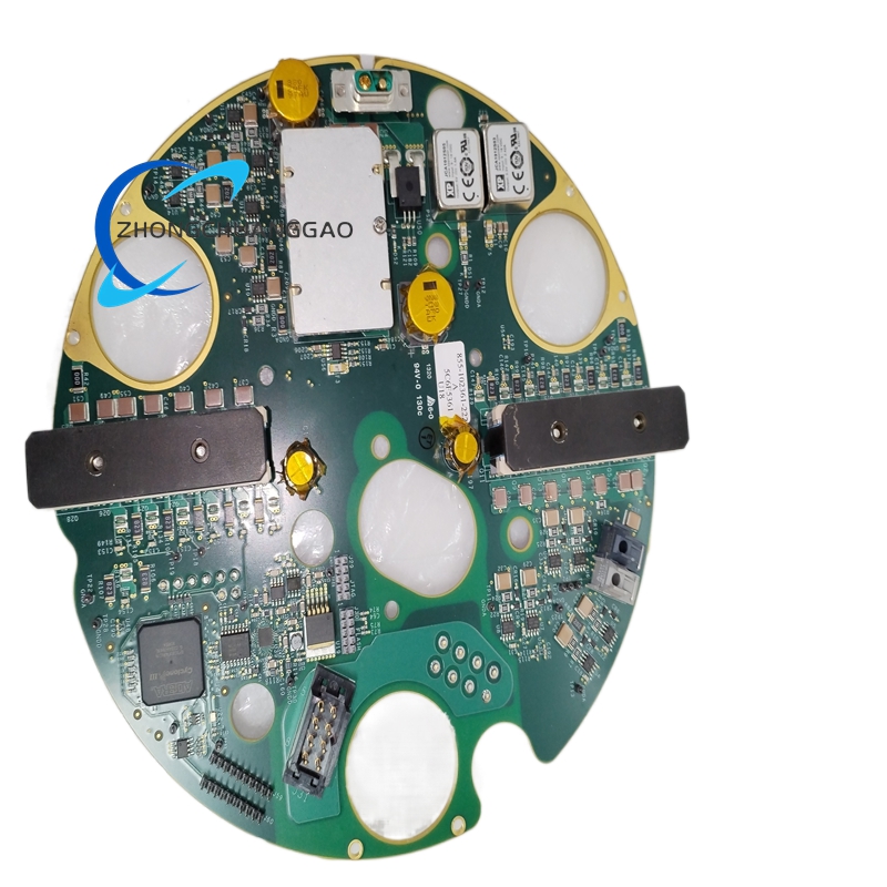
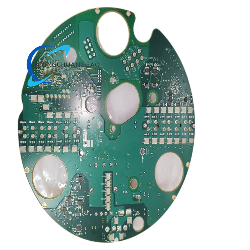
Multi-layer isolated analog and digital switching planes suppress electromagnetic interference. Gold-plated edge connectors provide repeatable backplane contact. Industrial conformal coating protects against moisture and chemical outgassing. RF match variant uses motor or piezo-driven variable capacitance for automatic tuning.
Application Scenarios
Used in dielectric etch, conductor etch, atomic layer etch and general plasma chamber telemetry management. Suitable for cleanroom semiconductor lines requiring precise sensor multiplexing and stable RF power transfer.
Performance Parameters
Multiplexer operating ambient is 10 to 50 degrees Celsius. Match variant cooling is water cooled in listed builds and forced air or water interface in integrated RF systems. Telemetry switching is designed for deterministic chamber feedback with minimal signal delay.
Material Composition
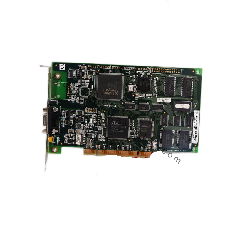
Multi-layer printed circuit board, surface-mount and through-hole electronic components, gold-plated contact fingers, isolated ground planes and full industrial conformal coating.
Structural Characteristics
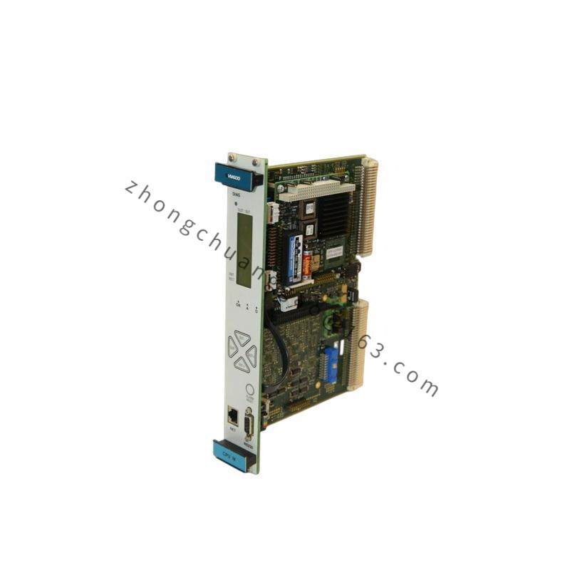
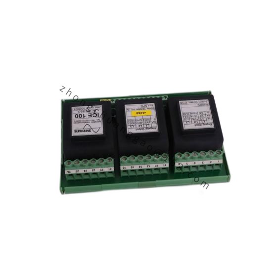
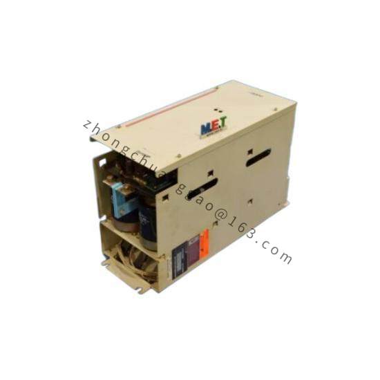
Card-cage plug-in construction with high-density edge connector and interface headers. RF match version uses enclosed network housing with variable capacitors, inductors, sensors and cooling ports.
Working Principle
The multiplexer assigns chamber sensor inputs to controller channels through analog switches and isolated planes, preventing crosstalk between sensitive signals. The match version measures forward and reflected RF power, then adjusts internal capacitance and inductance so the plasma load appears as 50 ohms to the generator.
Installation Requirements
Power down the rack before insertion or removal. Align the board with guide rails and seat the edge connector squarely. Verify hardware revision, firmware version and system software compatibility. For RF match installation, connect cooling lines, RF ports and communication cables according to the OEM manual.
Usage Precautions
Do not hot-swap the board with rack power energized. Avoid angular insertion that can bend backplane pins or damage gold fingers. Confirm firmware and configuration files before startup. Inspect conformal coating, connectors and capacitor or inductor condition during preventive maintenance.