Technical Specifications
DC Supply Range
48 to 325 VDC.
AC Supply Range
48 to 240 VAC single or three phase according to variant.
Logic Supply
24 VDC plus or minus 10 percent.
Motor Support
Two or three phase brushless synchronous motors, synchronous linear motors and brushed DC servo motors.
Continuous Power Class
Up to 7.1 kW depending on supply variant.
Digital Inputs
Six isolated digital control inputs.
Digital Outputs
Three isolated digital control outputs.
Analog Inputs
Two analog command inputs, minus 10 to plus 10 V, 10 bit resolution.
Analog Monitor Outputs
Two analog monitoring outputs, minus 10 to plus 10 V.
Encoder Interfaces
Incremental RS422 and SinCos, absolute BISS or HIPERFACE, plus encoder output for master slave operation.
Communication Interfaces
CANopen, EtherCAT, PROFIBUS, Ethernet, RS485 and RS232.
Safety Function
STO Safe Torque Off compliant with EN 61800-5-2, SIL2.
Functional Features
Motion Control
Executes position, velocity and torque control with integrated technology functions.
Sequence Programming
Performs subcontroller tasks without external PLC for many drive routines.
Diagnostic Feedback
Monitors temperature, current, encoder signals, communication state and safety circuit status.
Application Scenarios
Machine Tools
Spindle feeds, rotary axes and precision positioning tables.
Packaging Machines
Synchronized servo drives for filling, labeling and cutting stations.
Robotics And Automation Cells
Multi axis motion with EtherCAT or CANopen coordination.
Performance Parameters
Single Phase 230 VAC Variant
Rated input current 8 A, installed load 1.84 kVA, power loss 70 W.
Three Phase 230 VAC Variant
Rated input current 8 A, installed load 3.0 kVA, power loss 106 W.
DC 325 V Variant
Rated installed load 3.25 kW, power loss 92 W.
STO Response
Safe torque off through dedicated dual channel inputs and monitored feedback output.
Structural Features
Power Section
PWM inverter stage with DC bus capacitors, IGBT modules and cooling structure.
Control Section
Processor board with encoder decoding, fieldbus interface and safety logic.
Operator Connections
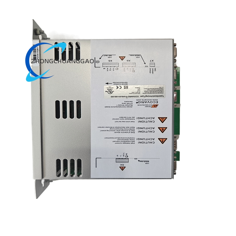
Removable terminals, encoder connectors, network ports and status LEDs.
Material Composition
Housing
Aluminum heat sink and coated steel mounting structure.
PCB
Multilayer industrial printed circuit boards with conformal protection.
Power Devices
Silicon IGBTs, rectifiers and low loss bus capacitors.
Connectors
Nickel or gold plated contacts with strain relief.
Working Principle
The amplifier receives command signals from a controller or internal sequence program, compares them with encoder feedback, calculates position velocity and torque errors, generates PWM voltage to the motor windings, regulates current through the DC bus and disables output immediately when the STO circuit is activated.
Installation Requirements
Mount on a flat panel or cabinet surface with adequate clearance for airflow. Select AC or DC supply variant before wiring. Connect motor power, encoder feedback and protective earth separately from signal cables. Install STO circuits according to EN 61800-5-2 and local machine safety rules. Configure drive parameters with JAT ECOSTUDIO software.
Usage Precautions
Verify supply voltage matches the amplifier variant before energizing. Never bypass STO wiring. Use correct encoder type and cable shielding. Avoid overloading output current beyond the rated power class. Perform commissioning with limited torque until motor direction and feedback polarity are confirmed.