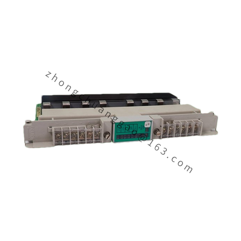
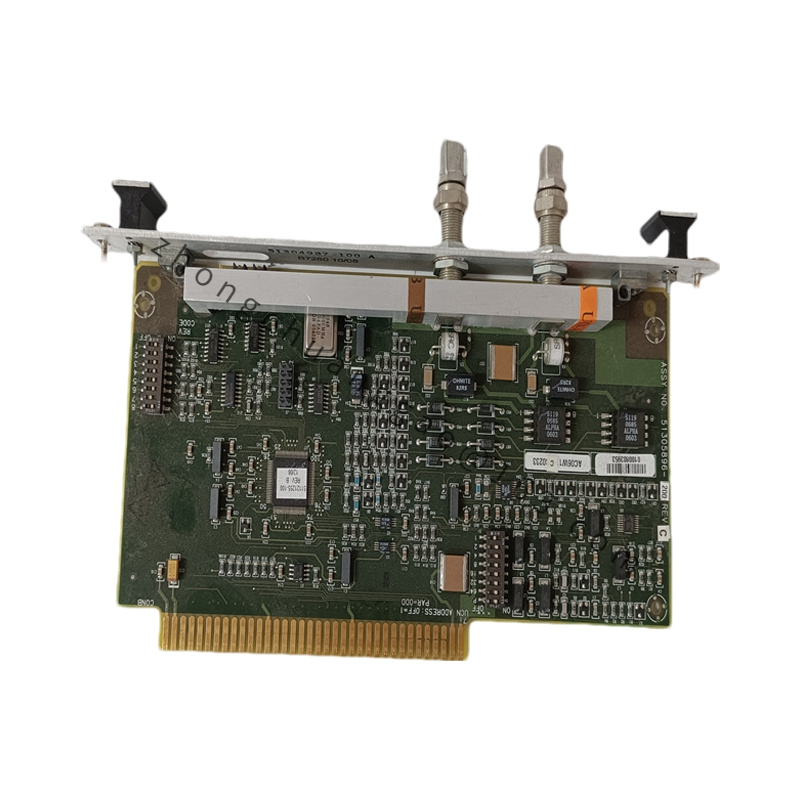
Introduction: This board is a high-reliability discrete signal acquisition interface for Experion PKS and TDC 3000 distributed control systems. It captures 24 VDC on/off signals from field sensors, limit switches, and auxiliary contacts, and converts them into logic-level data for the controller.
Indicators: 16 green channel LEDs plus one group status LED
Features: Each channel incorporates a programmable debounce filter (0–100 ms) for switch-bounce suppression. The board detects pulses with a minimum width of 2 ms and supports change-of-state capture. Filter settings are stored in non-volatile memory. A built-in loop test facility verifies field wiring integrity. The PCB is protected by a conformal coating for moisture and contaminant resistance.
Applications: Factory automation, building automation, steel plant high-temperature workshops, wind turbine nacelles, and other electrically noisy or harsh industrial environments.
Working Principle: The module receives 24 VDC field signals, conditions them through optical isolation, applies software-configurable filtering, and transfers the resulting logic state to the controller via the backplane. Internal capacitors bridge brief power interruptions and retain input state during supply dips.
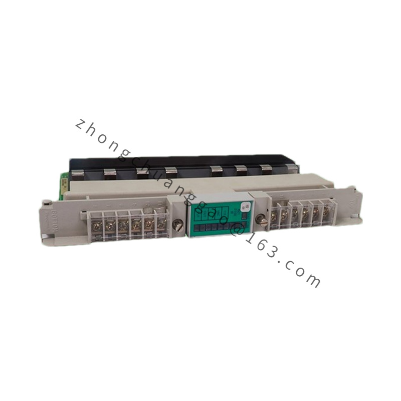
Installation Requirements: Insert the board into any available Series T I/O chassis slot. Press firmly until the ejector tabs engage, then tighten the two retaining screws. Connect the 40-pin field wiring harness after the board is seated. Verify the power LED illuminates after system energization. Use twisted-pair or shielded cable; ground shields only at the marshalling cabinet to prevent ground loops.
Precautions: Maintain ambient temperature within 0°C to +60°C and relative humidity 5–95% non-condensing. Avoid exceeding the 32 VDC input ceiling. Inspect connectors and wiring periodically. Replace the board promptly if any channel exhibits erratic behavior.

.jpg)
.jpg)
.jpg)

.jpg)

