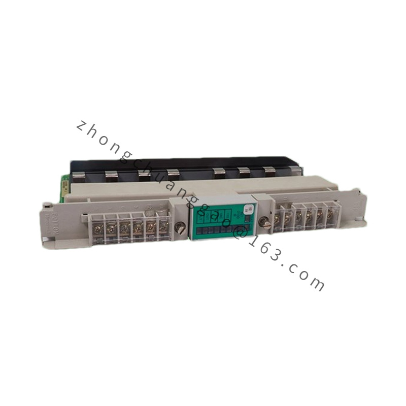
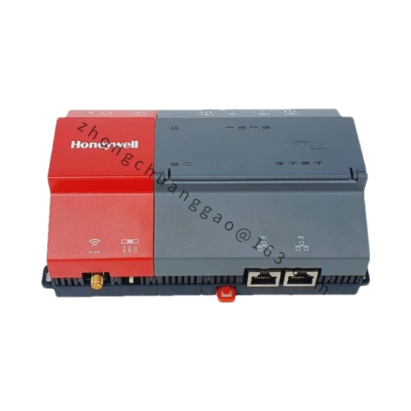
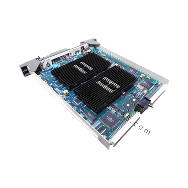
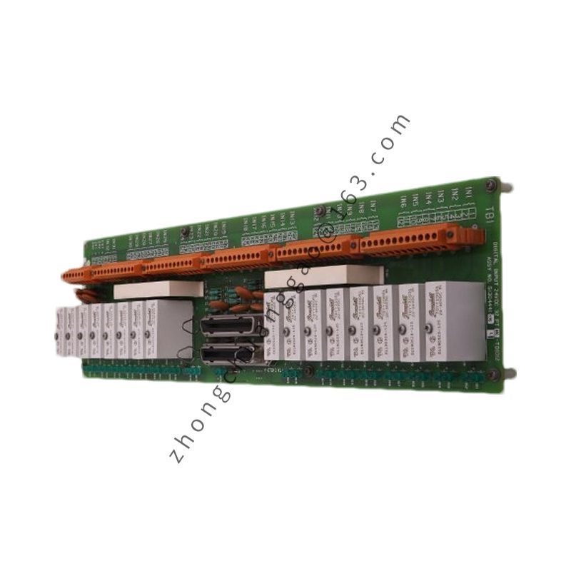
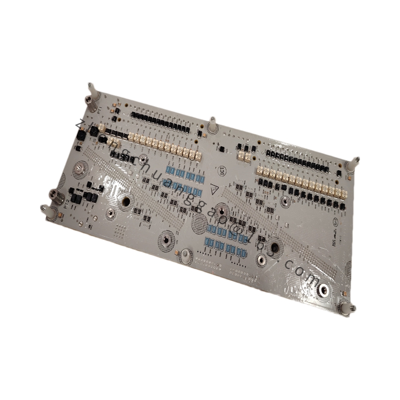
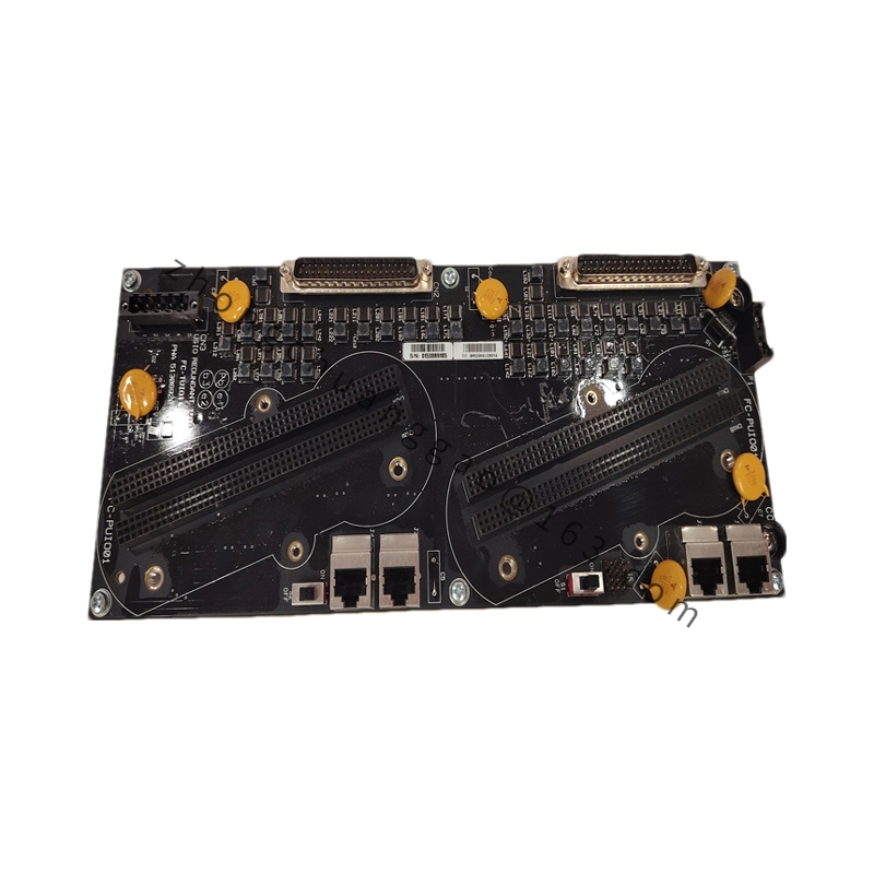
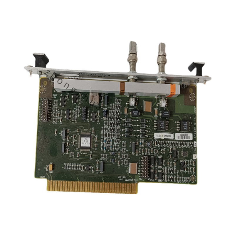
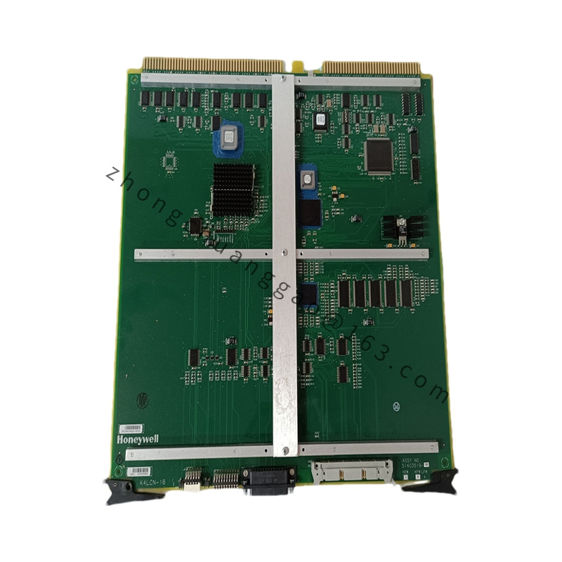
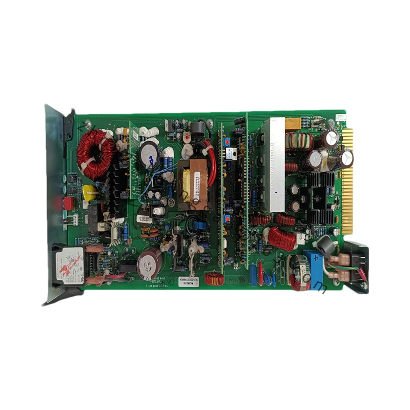
Product Introduction: This module provides 8 independent pulse-counting channels for Honeywell TDC3000, TPS, and Experion PKS distributed control systems. It accurately captures high-speed pulse signals from flow meters, tachometers, and encoders, converting them into DCS-readable count values for real-time monitoring of flow, speed, position, and totalization.
Functional Features: Supports frequency, period, and total pulse count measurement modes. Built-in signal filtering and debounce circuitry eliminate mechanical contact bounce and EMI. Loop monitoring detects open-circuit and short-circuit faults. Power-loss trip ensures a safe “0” state, meeting SIL 2/3 functional safety requirements per IEC 61508. Hot-swappable design allows replacement without system shutdown.
Application Scenarios: Used in petrochemical, power generation, metallurgy, and process industries requiring high-precision pulse acquisition—flow totalization, rotational speed measurement, and position feedback.
Structural & Material Characteristics: Compact DIN rail design with FTA screw terminals for fast, reliable field wiring. Conformal-coated PCB resists humidity and corrosion. Industrial-grade construction with wide-temperature tolerance.
Working Principle: Each of the 8 channels independently captures 24 VDC pulse signals through optically isolated inputs. The on-board processor counts pulses, calculates frequency/period, and transmits processed data over the UCN/backplane bus to the DCS controller.
Installation Requirements: Plug into a standard DCS system rack. Ensure proper DIN rail mounting inside a control cabinet with IP20 or higher enclosure rating. Verify backplane power before insertion.
Usage Notes: Use shielded cable for field pulse wiring. Maintain separation between signal and power cables. Confirm channel configuration (input type, counting mode, filter parameters) before commissioning. Observe ESD precautions during hot-swap replacement.

.jpg)
.jpg)
.jpg)