Digital guide

You are here:

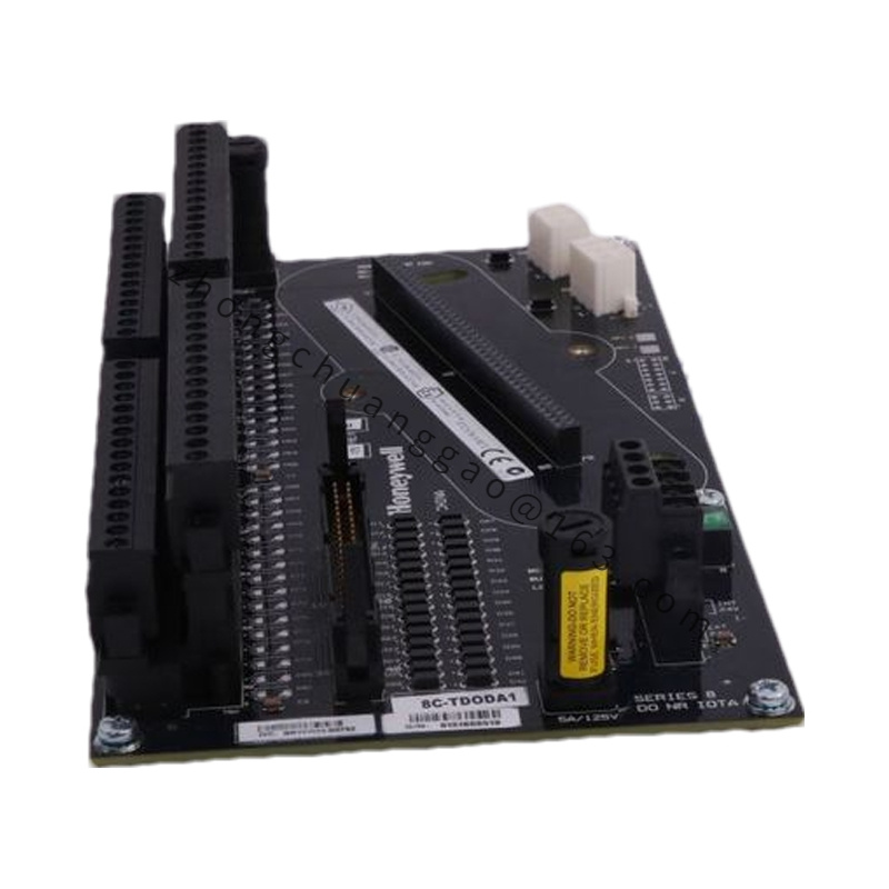
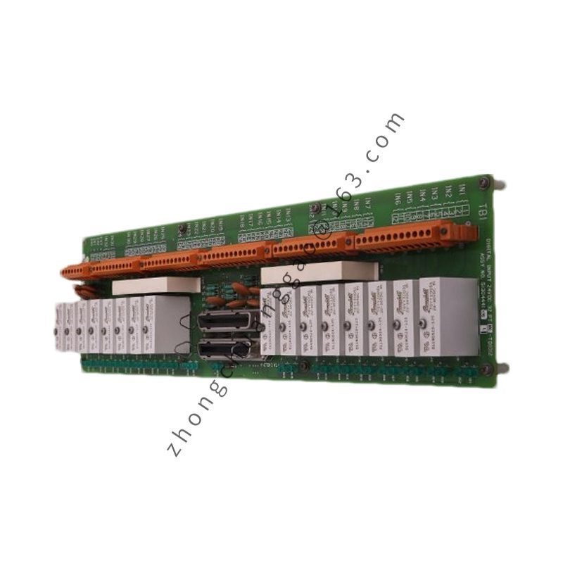
Honeywell 51204162-175

Product Name: 32-Channel Digital Output Field Termination Assembly (alternate: MC-TDOY22)
Overview: A specialized 32-channel Digital Output Field Termination Assembly (FTA) engineered specifically for Honeywell’s legacy TDC 3000 Distributed Control System (DCS) architecture. Handles isolated 24 VDC discrete control loops, providing a reliable physical interface between system Input/Output Processors (IOP) and plant final control elements such as solenoid valves, indicator lamps, and interlock relays.
Detailed content

Technical Specifications:
  • Module Type: Digital Output Field Termination Assembly (DO FTA)
  • Compatible Platform: TDC 3000 Distributed Control System (APM / HPM framework)
  • Number of Channels: 32 Isolated Digital Output Channels
  • Operating Voltage: 24 VDC discrete output loops
  • Isolation Type: Galvanically Isolated Channels
  • Compliance & Protection: CE Compliant, Conformal Coated (CC) for corrosive environments
  • Operating Temperature: 0°C to +60°C (+32°F to +140°F)
  • Origin of Manufacture: United States / USA
Key Features: The -175 suffix designates that the board is a CE-compliant, conformally coated variant built for enhanced durability in corrosive industrial environments. Built-in galvanic isolation protects system electronics from field voltage transients and ground loops.
Application Areas: Interfaces TDC 3000 controller outputs to 24 VDC field devices like solenoids, indicator lamps, and interlock relays.

Installation & Operation Guidelines:
  1. System Power Isolation: Ensure that cabinet power rails and external loop power supplies are completely de-energized before mounting or servicing the FTA assembly to prevent accidental equipment damage or short circuits.
  2. DIN Rail or Panel Mounting: Securely mount the FTA board within the designated marshalling or termination cabinet panel following standard structural guidelines.
  3. Field Wiring Connection: Terminate field actuator control lines and system interconnection cables to the designated screw terminal blocks, ensuring proper wire sizing and shielding for noise immunity.
  4. Diagnostic Verification: Power up the control system and inspect the associated I/O processor and FTA status indicators to verify normal communication handshaking and correct output actuation states.

You may also like