Technical Specifications
- System platform: Honeywell MasterLogic-200 / 200R
- Program memory: 7 MB
- Flash memory: 16 MB
- Data memory: 2 MB
- Total managed memory: 25 MB including system reserves
- Basic instruction execution: approximately 0.042 µs per step
- Maximum I/O bases: 31
- Maximum slots: 372
- Maximum local base I/O points: 23,808 with 64-channel modules
- Maximum network/remote I/O points: 128,000
- Programming languages: Ladder Diagram, Sequential Function Chart, Structured Text, Instruction List
- Execution modes: cyclic scan, time-driven interrupt, memory/event interrupt, direct I/O refresh
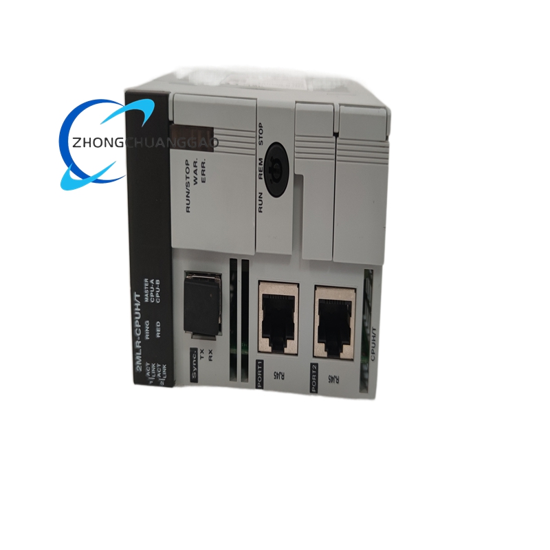
- Built-in ports: RS-232C, USB, Ethernet; redundant builds add fiber sync
- Redundancy synchronization: 1 Gbps multimode fiber, LC connector, 62.5/125 µm, up to 200 m
- Redundancy switchover: approximately 22 ms
- Backplane current: approximately 1173 mA at 5 VDC
- Backup battery: 3.0 V lithium manganese, 1800 mAh
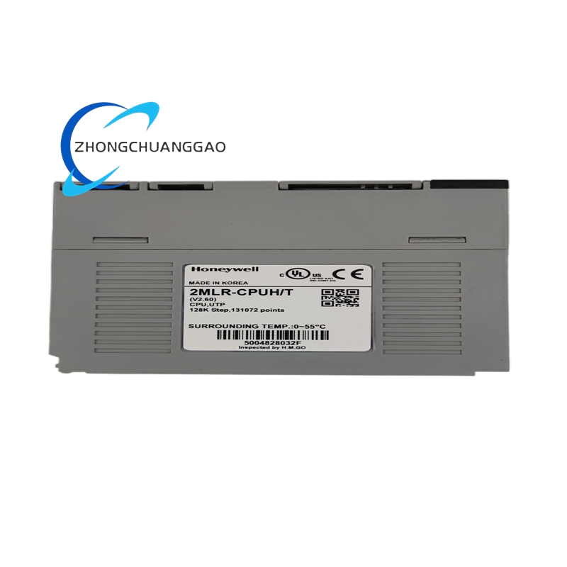
- Standard operating temperature: 0°C to 55°C
- Extended-temperature builds: -20°C to 70°C
- Storage temperature: -25°C to 70°C standard builds, wider ranges per special version
- Humidity: 5% to 95% RH, non-condensing
Functional Features
Large program and flash memory support complex process logic. Fiber redundancy provides bumpless transfer to standby CPU. Multiple interrupt sources reduce event latency. Extensive I/O capacity suits large distributed control and safety-related automation.
Material Composition
The module uses a metal/plastic controller housing, multilayer FR4 PCB, gold-plated backplane connectors, lithium backup battery and industrial-grade semiconductors.
Structural Characteristics
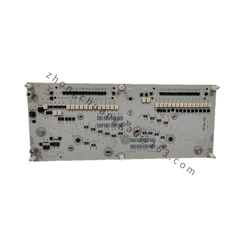
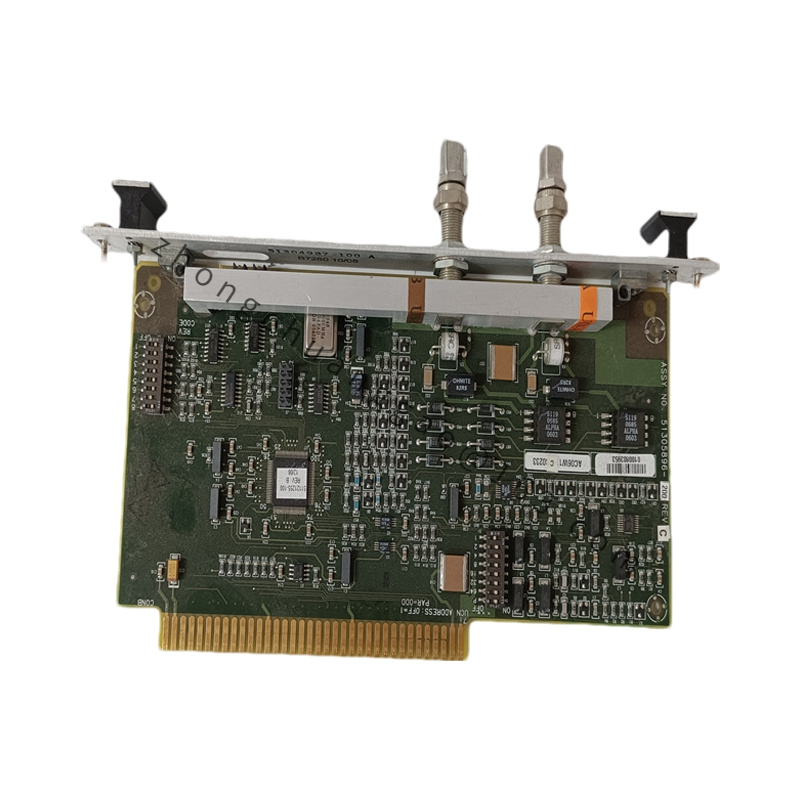
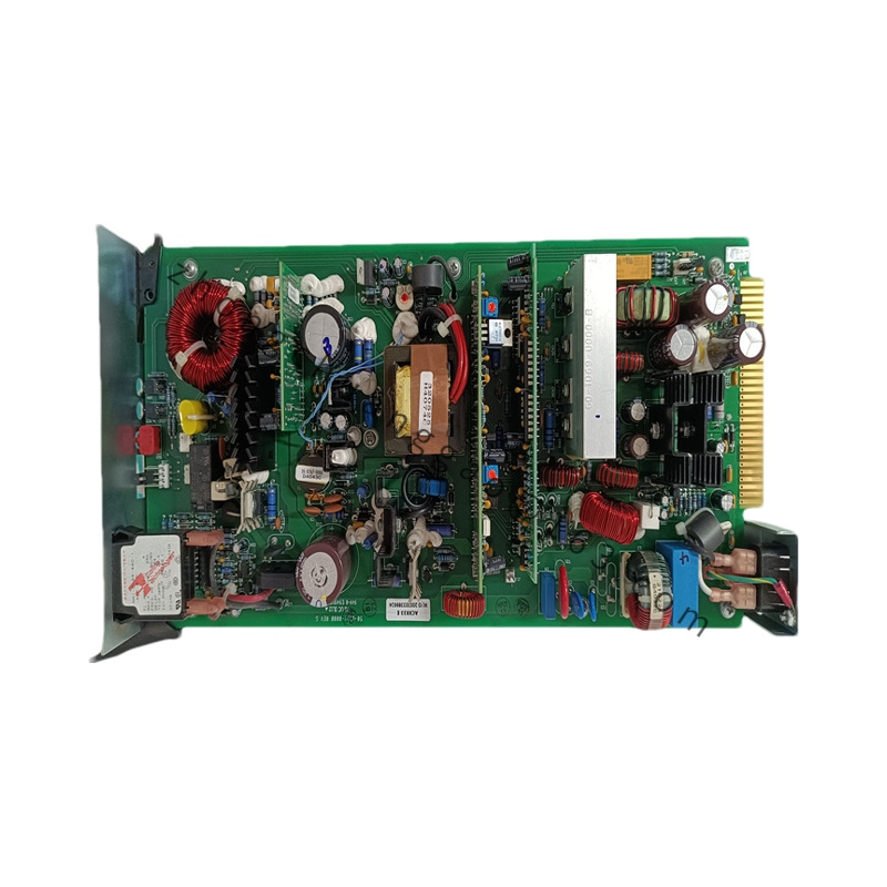
The CPU board contains processor, memory, communication controllers, status LEDs, battery holder and backplane connector. Redundant versions add a fiber synchronization module and duplicate data path.
Working Principle
The processor reads inputs through the backplane or network, executes the configured control program by scan cycle or interrupt, updates outputs and writes diagnostic data. In redundant mode, the primary CPU continuously copies memory image and I/O state to the standby CPU through the fiber link. On primary fault, the standby takes control without restarting the process cycle.
Installation Requirements
Power down the controller rack before insertion. Align the module with the CPU slot and press until the backplane connector seats fully. Engage locking latches. Connect battery, Ethernet, RS-232/USB and redundancy fiber as designed. Ground the cabinet to the plant earth bar with low-impedance conductor.
Usage Notes
Use firmware versions matched to the MasterLogic project. Validate redundant synchronization LEDs before process start. Do not remove the primary CPU under load unless redundancy is healthy. Protect the lithium battery from short-circuit and replace according to scheduled maintenance.

.jpg)
.jpg)