Honeywell 060-J576-09
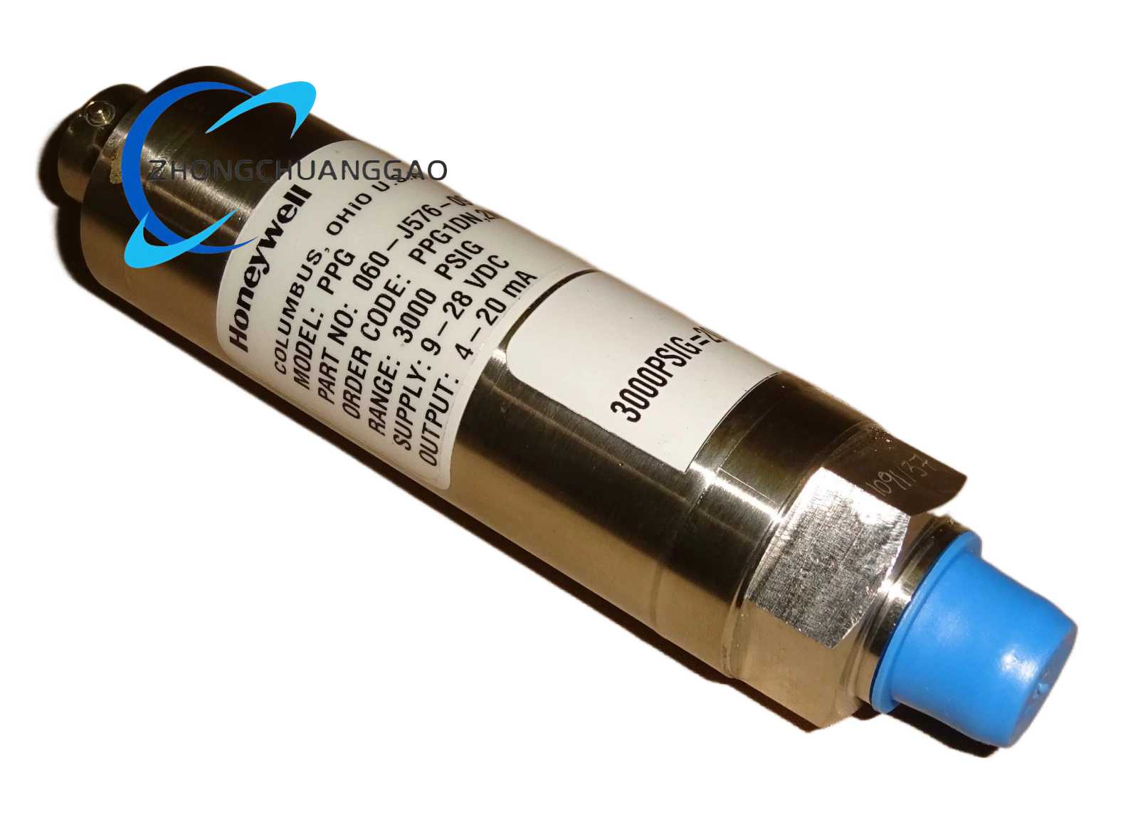
Product Description: This is a premium-grade pressure transmitter module manufactured by Honeywell Process Solutions, designed for continuous and accurate measurement of gauge pressure in industrial process media. The unit integrates a high-stability piezoresistive sensing element with onboard signal conditioning electronics that convert the raw sensor output into a robust 4 to 20 milliampere current loop signal suitable for transmission over long cable runs to distributed control systems. Its construction is optimized for harsh environments including exposure to corrosive fluids, temperature extremes and mechanical vibration.
Detailed content
Technical Specifications: Pressure measurement range 0 to 10 bar gauge with zero-based span, output signal 4 to 20 milliamperes DC two-wire loop powered, supply voltage 12 to 36 volts DC with minimum 12 volts required for operation, measurement accuracy 0.25 percent of span including linearity hysteresis and repeatability, temperature compensation range minus 40 to 85 degrees Celsius, zero and span temperature coefficients less than 0.02 percent per degree Celsius, process connection M20 by 1.5 millimeter male thread, electrical connection via M12 4-pin connector or cable gland entry.
Functional Features: 316L stainless steel wetted diaphragm provides excellent resistance to a wide range of industrial chemicals including acids alkalis and organic solvents, built-in temperature sensor enables real-time thermal drift compensation without external configuration, overpressure protection rated at 3 times full scale meaning the transmitter survives accidental pressure spikes up to 30 bar without permanent damage, reverse polarity protection prevents damage if wiring is connected incorrectly, EMC immunity per IEC 61000-6-2 for installations near variable frequency drives and welders, optional HART communication protocol available for remote configuration and diagnostics.
Application Scenarios: Deployed throughout petrochemical refineries for monitoring pipeline pressure in crude oil distillation and catalytic cracking units, used in HVAC systems of commercial buildings to control chilled water and heating hot water pump discharge pressures, applied in hydraulic press systems in manufacturing plants to ensure consistent clamping force through pressure feedback, utilized in pharmaceutical clean-in-place systems for verifying sanitization cycle pressure levels, also installed in water and wastewater treatment facilities for filter bed differential pressure monitoring and pump station discharge control.
Performance Parameters: Long-term drift stability less than or equal to 0.1 percent of full scale per year ensuring calibration intervals of 12 months or longer, response time to 90 percent of final value within 100 milliseconds for step pressure changes, operating vibration tolerance 2g peak at 10 to 2000 hertz per IEC 60068-2-6, burst pressure rating 100 bar for the 316L diaphragm assembly, insulation resistance greater than 100 megaohms at 500 volts DC between signal terminals and housing, IP65 ingress protection rating meaning complete dust protection and water jet protection from any direction.
Material Composition: Pressure sensing diaphragm and process wetted parts fabricated from 316L austenitic stainless steel with electropolished surface finish for maximum corrosion resistance, ceramic insulation substrate isolates the piezoresistive strain gauge bridge from the process medium, signal conditioning electronics potted in epoxy resin within a stainless steel tube, outer housing constructed from powder-coated aluminum alloy with glass-filled polyamide end caps, cable entry glands made from nickel-plated brass with fluorocarbon O-ring seals rated for continuous immersion.
Structural Features: Compact cylindrical design approximately 50 millimeters in diameter and 80 millimeters in length excluding process connection, M20 by 1.5 process thread located at the bottom with optional flat diaphragm or sanitary flush mount configurations, electrical connection through top-mounted M12 connector with four pins for loop power and signal, internal electronics accessible only through the top cap which requires a special spanner tool to prevent unauthorized adjustment, strain relief bushing at cable entry to protect internal wiring from bending stress, status LED visible through a transparent window on the housing top.
Working Principle: Process pressure acts on the 316L stainless steel diaphragm causing it to deflect minutely in proportion to the applied force. This deflection is transferred through an incompressible fill fluid to a piezoresistive strain gauge bridge bonded to a ceramic substrate. The strain gauges change their electrical resistance as they are stretched or compressed by the diaphragm movement, creating an unbalanced Wheatstone bridge circuit. The resulting millivolt-level signal is amplified temperature-compensated and linearized by the onboard conditioning electronics, then converted to a proportional 4 to 20 milliampere current output that represents the pressure from 0 to 10 bar across the full measurement range.
Installation Requirements: Mount the transmitter at a location on the process pipeline that is accessible for periodic inspection and calibration, orient the unit so that the process connection is at the bottom to prevent air or vapor trapping in the sensing cavity, ensure that the process medium is compatible with 316L stainless steel before installation as the diaphragm is the only wetted barrier, install a shut-off valve upstream of the transmitter to allow isolation without draining the entire pipeline, the cable run to the control system should not exceed 1000 meters and must use twisted pair with individual shield if in a noisy electrical environment, torque the process connection to 25 Newton meters maximum.
Usage Precautions: Do not exceed the maximum rated pressure of 30 bar even temporarily as this will cause permanent deformation of the diaphragm and loss of calibration accuracy, never apply pressure to the unit before the electrical connections are properly made and verified, the transmitter must be recalibrated every 12 months using a certified pressure standard with accuracy at least four times better than the transmitter specification, avoid exposure to temperatures beyond the minus 40 to 85 degree Celsius range as the fill fluid properties change outside this window, if the unit is used with media containing solid particles a protective filter or snubber must be installed upstream to prevent diaphragm puncture.