Technical Specifications
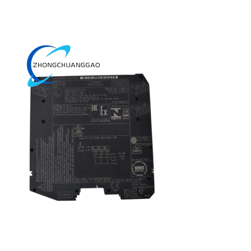
Brand: GM International
Model: D5091S
Channels: One
Safety Integrity: Up to SIL 3
Input Voltage: 24 VDC nominal
Input Voltage Range: 21.6–27.6 VDC
Reverse Polarity Protection: Yes
Current Consumption: 45 mA typical at 24 VDC
Power Dissipation: 1.1 W typical at 24 VDC
Output Type: Voltage-free SPDT relay contact
Contact Material: Cadmium-free silver alloy with gold plating
Contact Rating: 5 A at 250 VAC, 1250 VA
DC Contact Rating: 5 A at 250 VDC, 140 W resistive load
Minimum Switching Current: 1 mA
Inrush Current: 6 A at 24 VDC or 250 VAC
Operate Time: 55 ms typical
Release Time: 30 ms typical
Mechanical Life: 5,000,000 operations typical
Electrical Life: 30,000 operations typical
Input/Output Test Voltage: 2.5 kV
Hazardous Area Installation: Zone 2 / Division 2
Operating Temperature: -40–70 °C
Storage Temperature: -45–80 °C
Mounting: 35 mm DIN rail or custom termination board
Connections: Polarized plug-in screw terminal blocks
Conductor Size: Up to 2.5 mm² / 13 AWG
Dimensions: 12.5 mm wide × 123 mm deep × 120 mm high
Weight: Approximately 125 g
Functional Features
Safety Output Switching: Controls loads in safety instrumented or process shutdown systems.
NO and NC Contacts: Provides normally open and normally closed contacts for normally de-energized loads.
Service Contact: Includes an additional contact for non-safety service functions.
DCS/PLC Pulse Testing: Internal circuitry supports line pulse testing without causing contact or LED flicker.
I/O Isolation: Separates the control input circuit from the output contact circuit.
Hazardous Area Suitability: Supports installation in applicable Zone 2/Division 2 locations.
Application Scenarios
Functional safety: Emergency shutdown and safety interlock circuits
Oil and gas: Safety valve and shutdown load switching
Chemical processing: High-risk process isolation and alarm systems
Industrial automation: Safety-related load switching interfaced to DCS or PLC systems
Material Composition
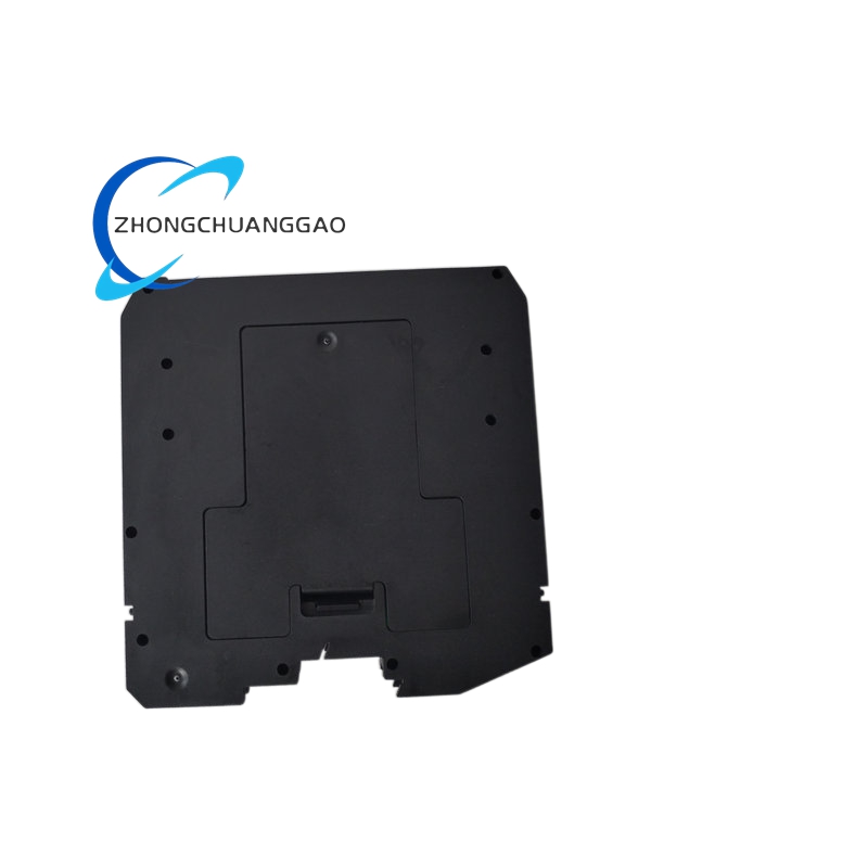
Housing: Industrial-grade plastic enclosure
Contacts: Silver alloy with gold plating
Terminals: Plug-in screw terminal blocks
Internal Protection: Suppressor diodes for relay coil protection
Structural Characteristics
Compact Design: 12.5 mm wide single-channel module
Removable Terminals: Allows plug-in termination for installation and maintenance.
DIN Rail Mounting: Installs horizontally or vertically on a 35 mm DIN rail.
Safety Contact Arrangement: Dedicated terminals for SPDT safety and service functions.
Working Principle
A 24 VDC control input energizes the internal safety relay coil. The relay changes the state of its contacts to energize or de-energize the connected safety load. Under the defined normally de-energized configuration, the safety state is achieved when the relay is de-energized.
Installation Requirements
Orientation: The module may be mounted in any orientation within the published temperature range.
DIN Rail: Mount on a 35 mm DIN rail or compatible termination board.
Wiring: Use the correct removable screw terminal block and verify wire gauge and torque.
Standards: Comply with applicable national and international electrical installation standards.
Load Rating: Confirm that the connected load does not exceed the contact’s voltage, current, and breaking capacity.
Protection: Use external overcurrent protection selected according to the load and breaking capacity.
Usage Precautions
De-energize First: Disconnect power before opening the enclosure or removing terminals.
Enclosure Protection: The module provides IP20 protection and normally requires additional protection outdoors.
Cleaning: Use only a slightly damp or antistatic cloth; avoid liquid ingress.
Unauthorized Modification: Do not modify the internal circuitry.
Hazardous Area: Follow all applicable hazardous-area installation rules.
Documentation: Verify the complete safety function, order code, and certification documentation before use in a safety instrumented system.