
compliant
• Data format: ANSI/IEEE 754-1985 32-bit floating-point
• Local timing: six programmable System Timing Controllers (STCs) each offering four high-speed counter / waveform synthesis ports
• Isolation: RS-422 differential or single-ended TTL I/O options
• Power: single-slot 6U VME, +5 V DC only
• Data format: ANSI/IEEE 754-1985 32-bit floating-point
• Local timing: six programmable System Timing Controllers (STCs) each offering four high-speed counter / waveform synthesis ports
• Isolation: RS-422 differential or single-ended TTL I/O options
• Power: single-slot 6U VME, +5 V DC only
2. Functional Highlights
• Continuous measurement mode runs without host CPU intervention, freeing system resources
• Command-driven memory-mapped user interface—no low-level timing programming required
• Real-time pulse-train, square-wave and PWM generation with programmable duty cycle
• Quadrature decoding for rotary shafts, linear encoders and robotic joints
• Built-in self-test and diagnostics accessible via VMEbus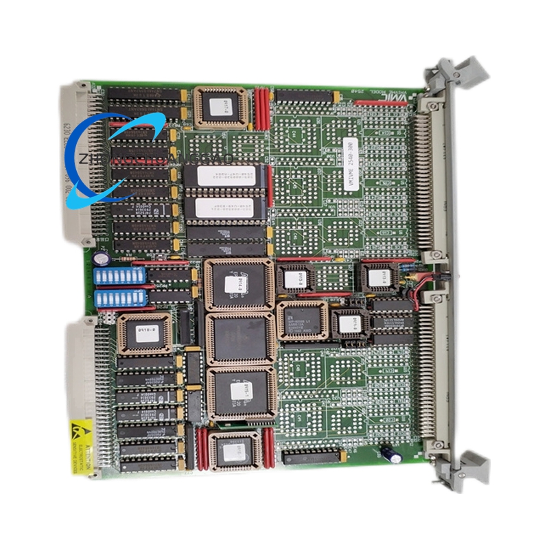
3. Application Scenarios
• Rotating machinery monitoring: angular position, velocity and acceleration on motors, turbines and spindles
• Automotive testing: brake, transmission and tachometer validation rigs
• Robotics: joint position feedback and trajectory generation
• Telescope / observatory: high-resolution tracking and pointing control
• Medical and laboratory instruments: precision timing and sample positioning
• Elevators, overhead cranes, X-Y tables, machine tools and automated storage/retrieval systems
4. Installation & Expansion
• Plugs directly into any standard 6U VME chassis; supports daisy-chained interrupt lines for multi-card synchronisation
• Firmware upgradeable in-system via VMEbus
• Compatible with VMIC VMIVME-7614 CPU boards and VMIVME-5588 reflective memory for distributed control
• Plugs directly into any standard 6U VME chassis; supports daisy-chained interrupt lines for multi-card synchronisation
• Firmware upgradeable in-system via VMEbus
• Compatible with VMIC VMIVME-7614 CPU boards and VMIVME-5588 reflective memory for distributed control
5. Ordering Package
• VMIVME-2540 module (channel count ordered as suffix)
• 6U VME front-panel kit and extraction lever
• User manual (paper and PDF)
• Factory calibration certificate
• VMIVME-2540 module (channel count ordered as suffix)
• 6U VME front-panel kit and extraction lever
• User manual (paper and PDF)
• Factory calibration certificate
