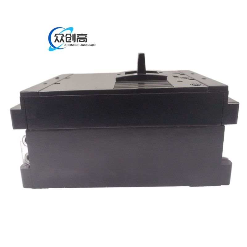
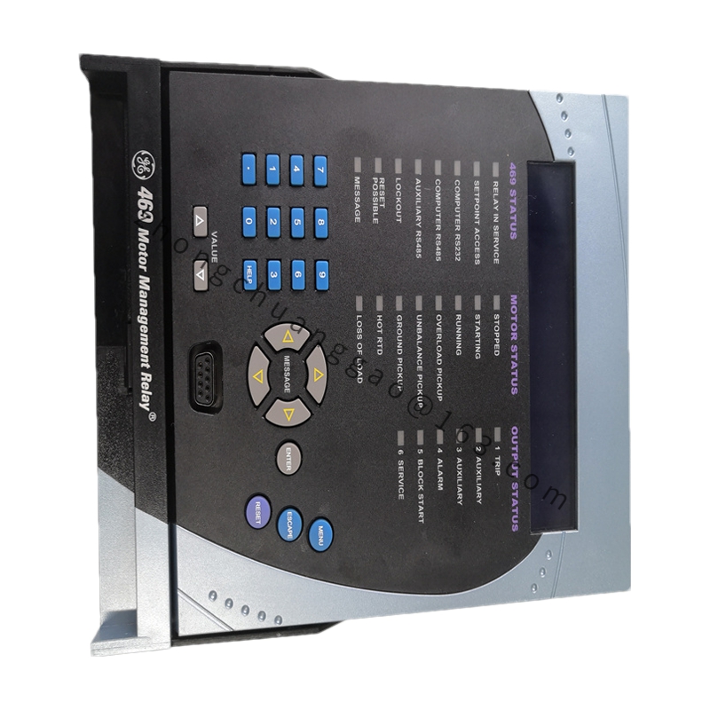
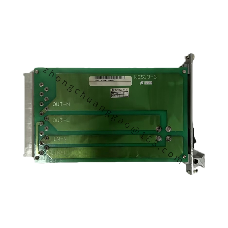
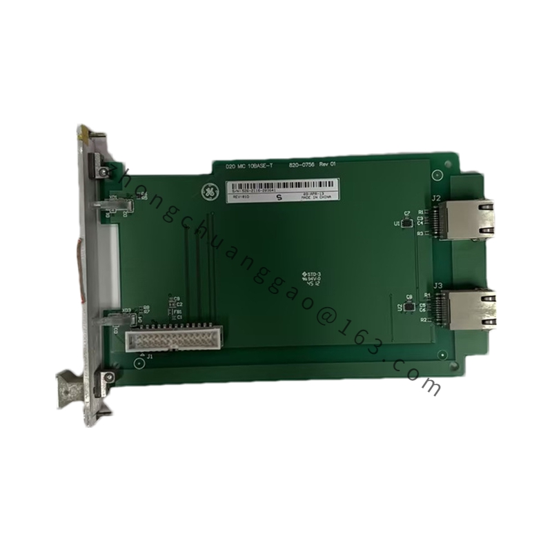
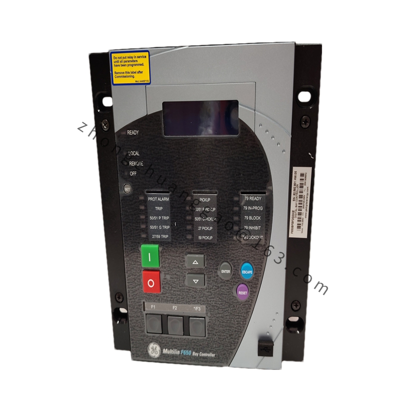
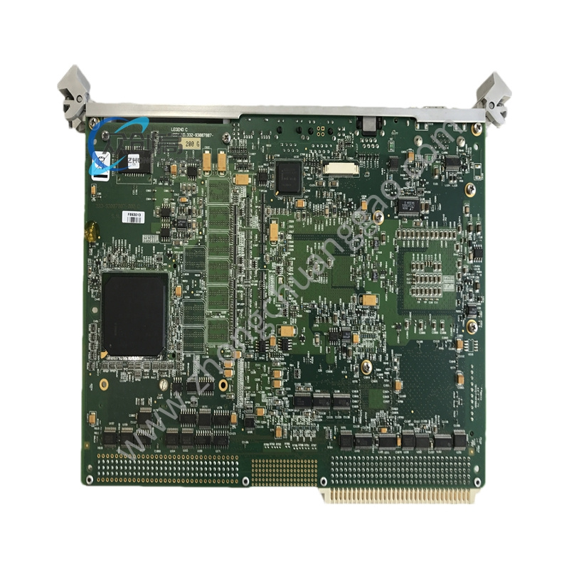
Product Name: TMQV32 Series Electronic Trip Unit (125 A)
Product Introduction: An electronic trip unit in the TMQV32 series, designed for use with GE Power Break II/III low-voltage frame circuit breakers. The suffix “125” denotes a 125 A rated current. It provides LSIG (Long-time, Short-time, Instantaneous, Ground) four-stage protection.
Short-circuit Breaking Capacity: up to 65 kA @ 480 V AC (in conjunction with the breaker)
Power Supply: Self-powered via current transformer (CT)
Optional Communication: Modbus RTU
Operating Temperature: –25 °C to +70 °C
Measurement Accuracy: ±5%
Instantaneous Trip Time: < 20 ms (at 2× setpoint)
Power Consumption: < 5 W
Communication Baud Rate: 9600 / 19200 / 38400 bps
Material Composition: Flame-retardant PC/ABS housing (UL94 V-0); FR-4 PCB with conformal coating; quick-connect plug-in connectors.
Structural Features: Modular plug-in design that fits Power Break II/III breakers; front-panel LED display with 4-key programming; bottom plug-in connection to the breaker.
Functional Features: LED digital display with 4-button programming; records up to 16 fault events; optional Modbus RTU remote communication.
Working Principle: The CT acquires current signals; the internal microprocessor calculates the four-stage protection conditions in real time and outputs a trip signal when any stage is triggered.
Application Scenarios: Feeder circuits in commercial buildings, industrial plants, and power distribution panels requiring selective coordination and ground-fault protection.
Installation Requirements: Install as a plug-in module into the designated slot of a compatible Power Break II/III breaker. Ensure proper torque on all terminal connections.
Usage Notes: Verify the current setting matches the protected circuit. For Modbus communication, ensure correct wiring polarity and baud-rate matching. Record fault event logs periodically for predictive maintenance.