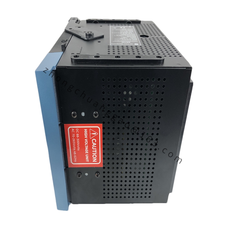
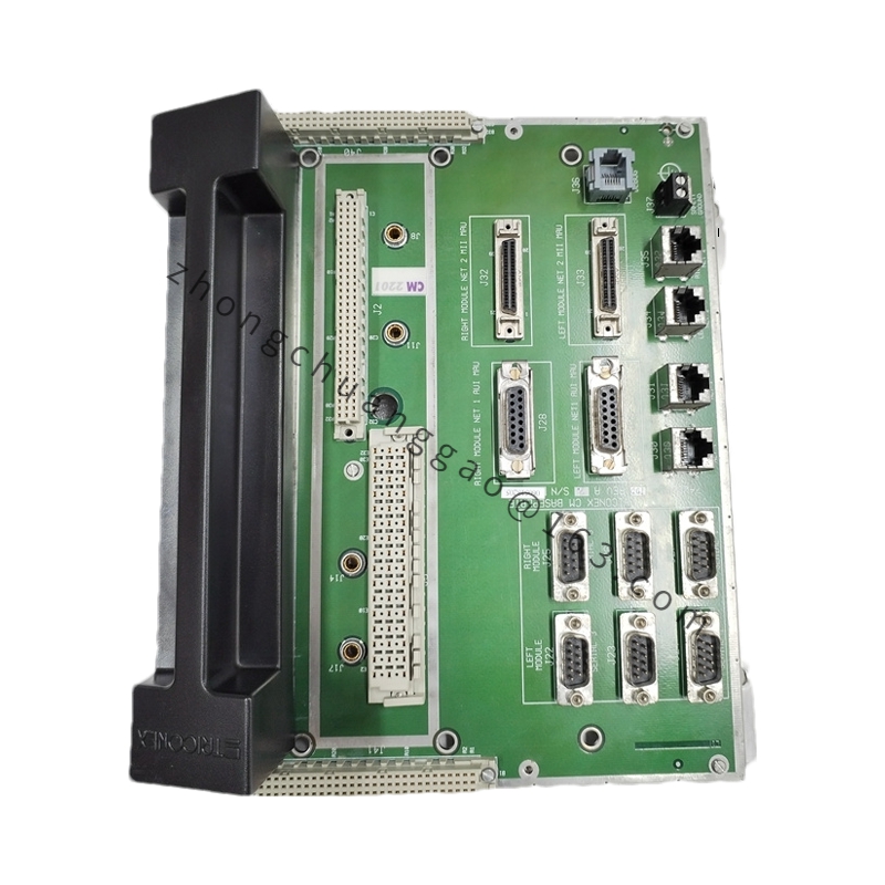
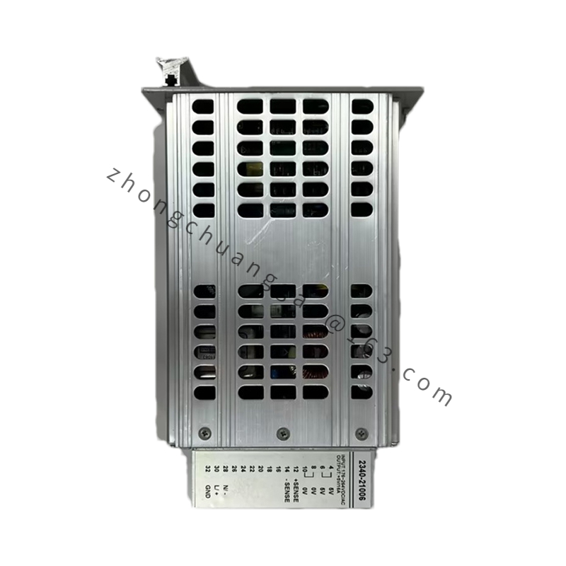
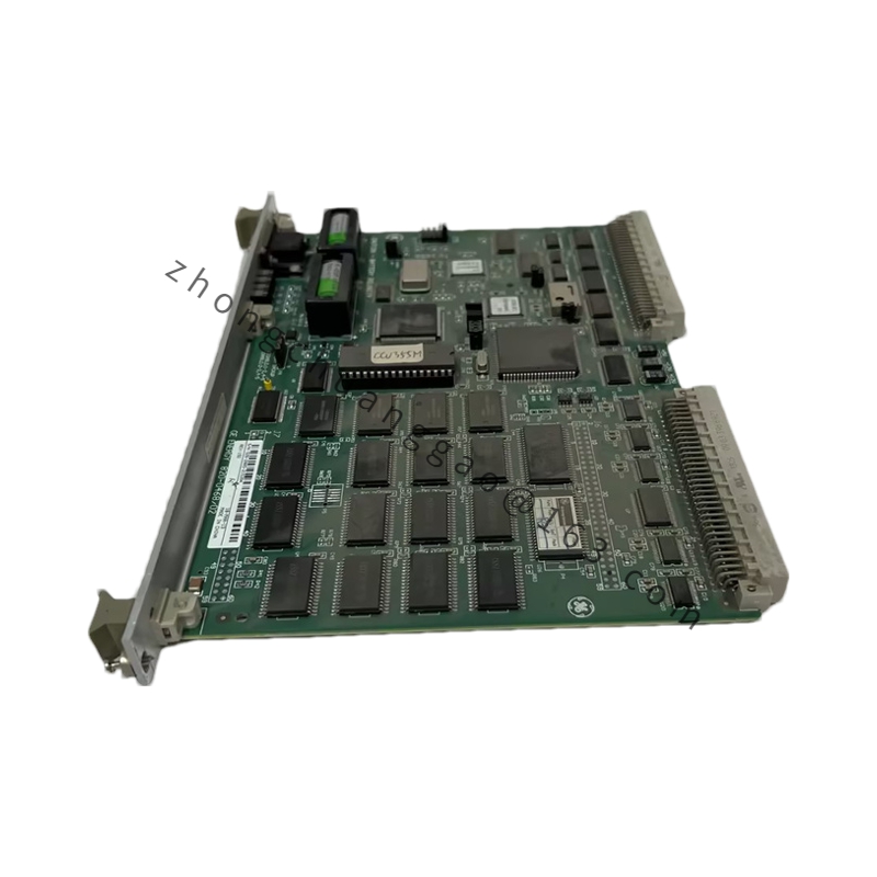
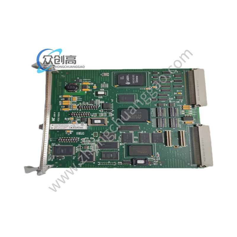
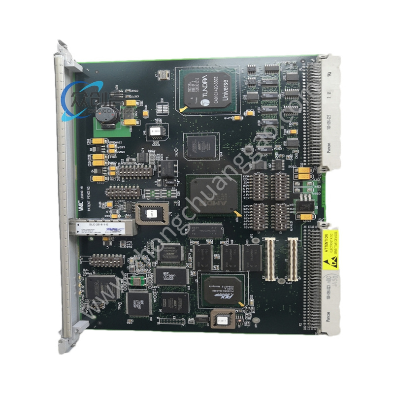
GE SR737-5-5-HI-485
Product Name: GE Multilin SR737 Digital Feeder/Overcurrent Protection Relay
Product Introduction: The SR737 is a digital feeder protection relay developed by GE Grid Solutions for primary circuit protection on distribution networks at any voltage level, and can also serve as backup protection for transformers and transmission lines. In the specific model “SR737-5-5-HI-485”, “5-5” denotes 5 A CT input / 5 A CT secondary rated current, “HI” indicates a high-impedance type suitable for long-cable CT circuits, and “485” denotes an RS-485 communication interface.
Detailed content
Technical Specifications:
-
Relay Type: Digital static overcurrent relay
-
CT Rating: 5 A / 5 A
-
Input Type: High-impedance (HI), supporting CT loop cable length > 300 m
-
Overcurrent Stages: Three-phase time overcurrent (51) + ground time overcurrent (51G)
-
Overcurrent Pickup Range: 0.5 A – 50 A (secondary side)
-
Definite-time Setting: 0.01 s – 30 s
-
Curve Types: ANSI, IAC, IEC/BS142
-
Curve Shapes: Definite time, moderately inverse, inverse, very inverse, extremely inverse
-
Communication Interface: RS-485 (Modbus RTU), baud rate up to 19,200 bps
-
Auxiliary Power: 48 V DC to 250 V DC/AC (wide range)
-
Operating Temperature: -20 °C to +70 °C
-
Protection Rating: IP50 (front panel)
-
Outputs: Trip, auxiliary trip, service; SR737 has 8 additional output relays
-
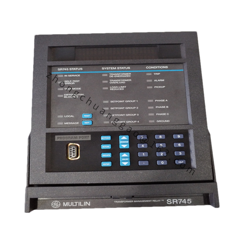
Indicators: 8 LED trip indicators + 4 LED status indicators + current bar graph (% of CT)
Functional Features:
-
Built-in three-stage overcurrent protection (Stage I definite-time, Stage II definite-time, Stage III inverse-time) with independent adjustment
-
Supports ground fault protection (50G/51G)
-
Fault waveform recording (oscillography) capturing current waveforms before and after the fault
-
RS-485 communication enables remote setting modification and condition monitoring
-
Front-panel LCD display for local parameter viewing and event logs
-
Draw-out construction minimizes replacement time
-
Built-in simulation features simplify field testing
Application Scenarios: Primary and backup protection of distribution network feeders, motor protection, generator protection, transformer protection, and industrial power distribution.
Installation Requirements: DIN rail mount or panel flush mount. CT ratio setting must exactly match the field CT. The high-impedance (HI) version must NOT be used in low-impedance CT circuits. Observe polarity when wiring the auxiliary power supply.
Usage Notes: Configure the CT ratio precisely according to the actual field CT. Use Modbus RTU protocol over RS-485 for integration into SCADA/DCS systems. Utilize GE’s EnerVista software suite for setup, oscillography retrieval, and event analysis.