GE IS210MVRCH1A
Product Name
GE IS210MVRCH1A MVRC High-Voltage Relay Control and Excitation Regulator Assembly
Product Introduction
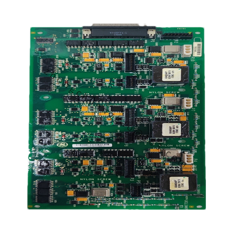
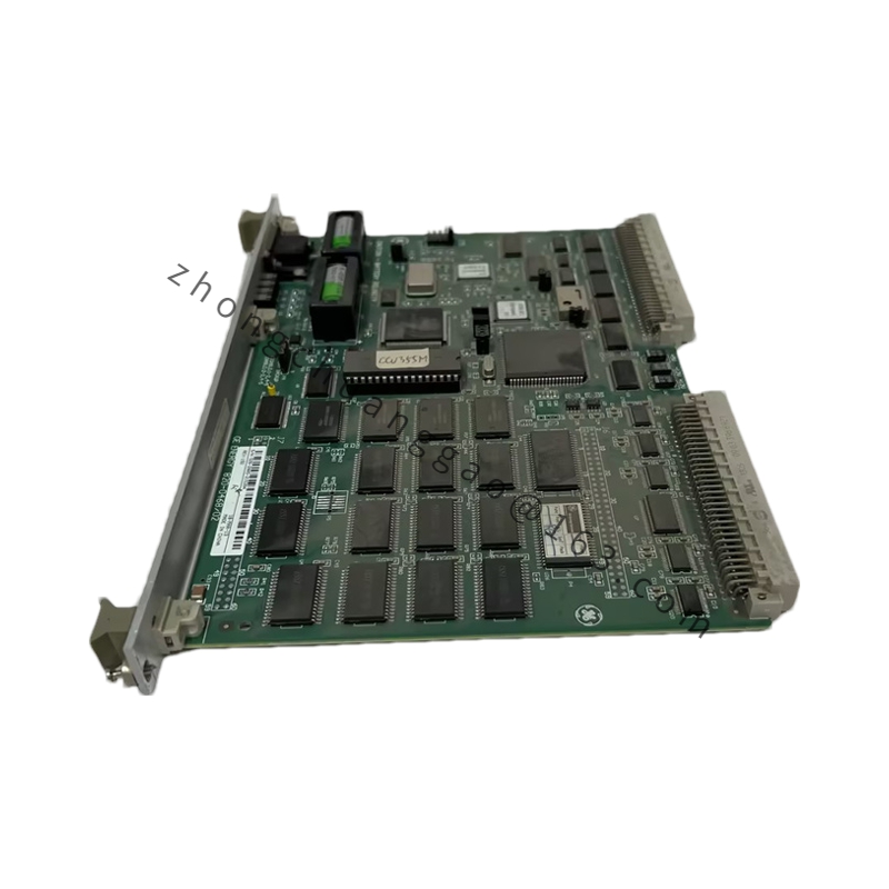
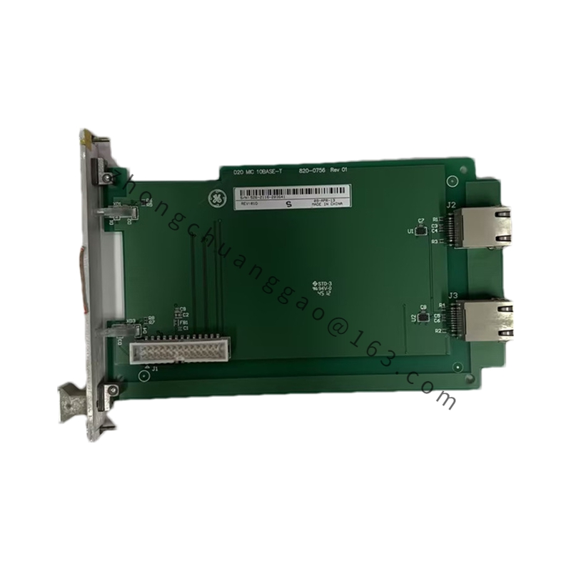
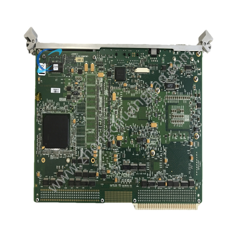
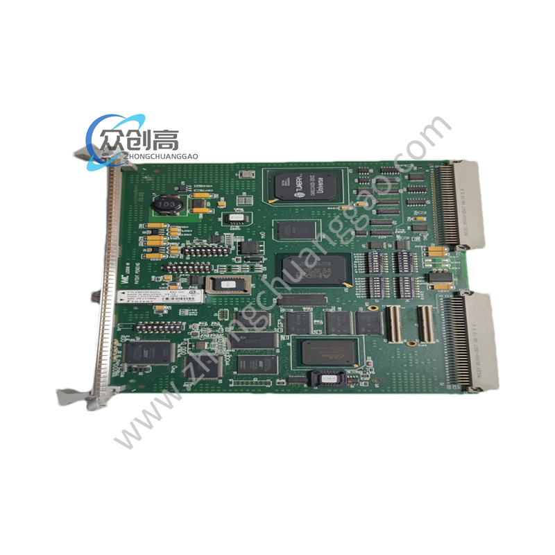
The GE IS210MVRCH1A is a Process Wiring Assembly (PWA) combining the IS200MVRC baseboard and IS200HSLA high-speed serial link board. It functions inside Mark VI / Mark VIe C-core racks as the excitation voltage regulator and high-voltage relay controller for EX2100 static exciter systems.
Detailed content
Technical Specifications
-
Input Signals: 3-phase VT 120 VAC, CT 5 A, DC field voltage 0–250 V
-
Output Drive: ±10 VDC / ±200 mA to thyristor firing stage
-
Regulation Accuracy: ±0.05 % of setpoint
-
Step Response: < 20 ms to 90 % of change
-
Control Modes: AVR, FCR, PSS (IEEE 2A/2B stabilizer)
-
Communication: HSLA high-speed serial, Ethernet Modbus/TCP, Profibus-DP option
-
Redundancy: hot standby switchover < 50 ms
-
Supply: 24 VDC ±10 % (15 W)
-
Operating Temperature: -30 °C to +65 °C
-
MTBF: 250,000 hours per IEC 61709
Functional Features
-
Maintains generator terminal voltage and reactive power sharing
-
Drives SCR firing pulses for field current regulation
-
Manages turbine-start high-voltage contactor logic via relay outputs
-
Continuous self-diagnostics on thyristor health and field insulation
-
Front LEDs: green run, yellow standby, red fault
Material Composition
-
Baseboard and HSLA daughterboard: FR-4 with IPC-CC-830B conformal coat
-
Aluminum mounting brackets (4 per assembly)
-
Gold-finger backplane edge connectors
-
Surface-mount DSP and FPGA devices
Structural Characteristics
-
Dual-board stack fixed by four mounting brackets
-
Ports: JC, JAA, JBB, JCC, JDD, JAR, JAS, JAT, optional JHH/JII
-
Occupies one C-core slot in Mark VIe VME rack
-
Weight under 5 lb
Working Principle
Generator VT/CT data and operator setpoints enter the MVRC baseboard, are exchanged with the controller over HSLA at millisecond scan, processed by PID + PSS algorithm, converted to ±10 V firing command, and forwarded to the EGDM gate-drive stage; high-voltage auxiliary relays for breaker control are switched through on-board contacts.
Application Scenarios
-
GE EX2100 and EX2100e exciter cabinets
-
Frame 7FA/9FB combined-cycle generator excitation
-
Steam turbine generator AVR replacement projects
Installation Requirements
-
Insert into C-core vacant location 2 with both brackets seated
-
Fiber HSLA cables must click into transceiver seats
-
24 VDC supply from isolated control power, not from thyristor DC bus
Usage Precautions
-
Treat as ESD-sensitive; no bare-hand contact with gold fingers
-
Verify field polarity before first AVR close-loop test
-
Do not run with HSLA fiber disconnected—causes exciter watchdog trip