Product Name: Redundant Power Supply Module (Mark VI Speedtronic)
Product Introduction: The IS2020RPSMG1A is a redundant power supply module for GE’s Mark VI / Mark VIe Speedtronic control systems. It provides stable, uninterrupted DC power to the entire control system and is a critical infrastructure component of the Speedtronic Mark VI platform.
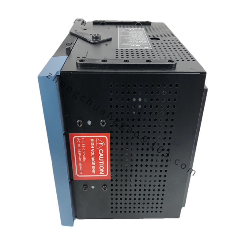
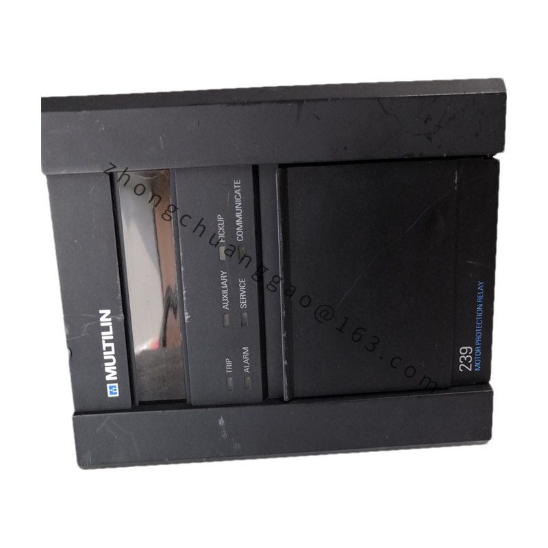
Metal chassis with removable front panel for maintenance
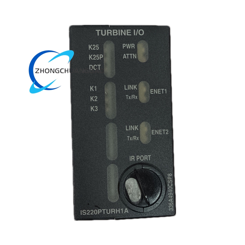
Four front-panel LED indicators plus one test button
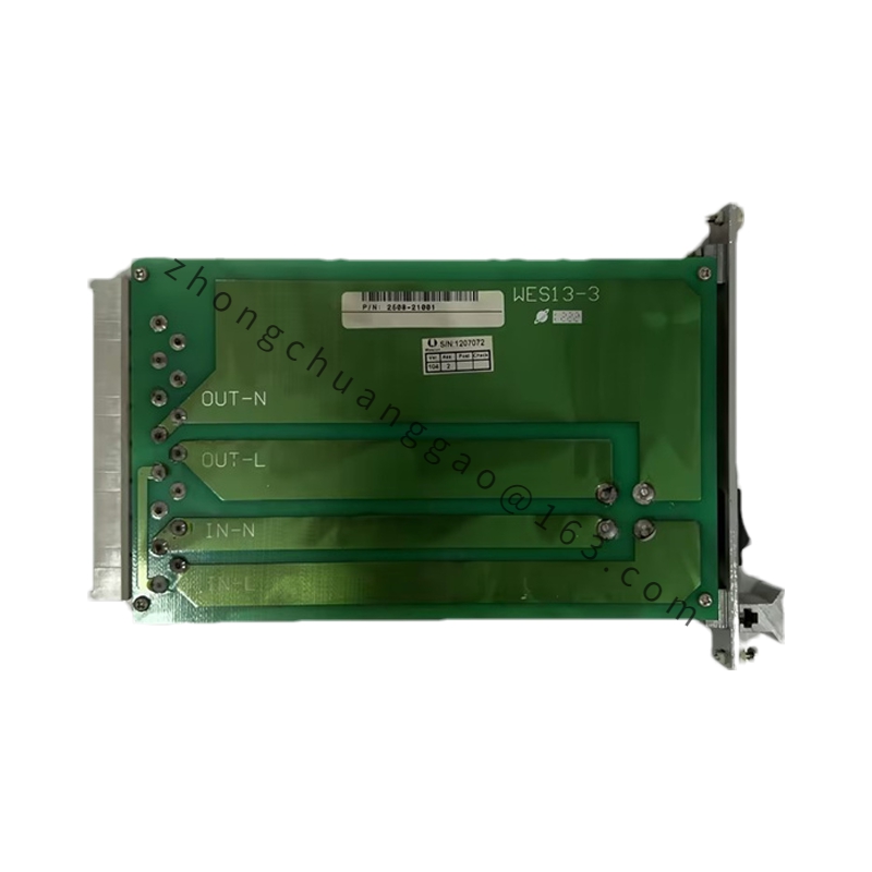
Rear panel: AC input terminals, DC output terminals, redundancy communication interface
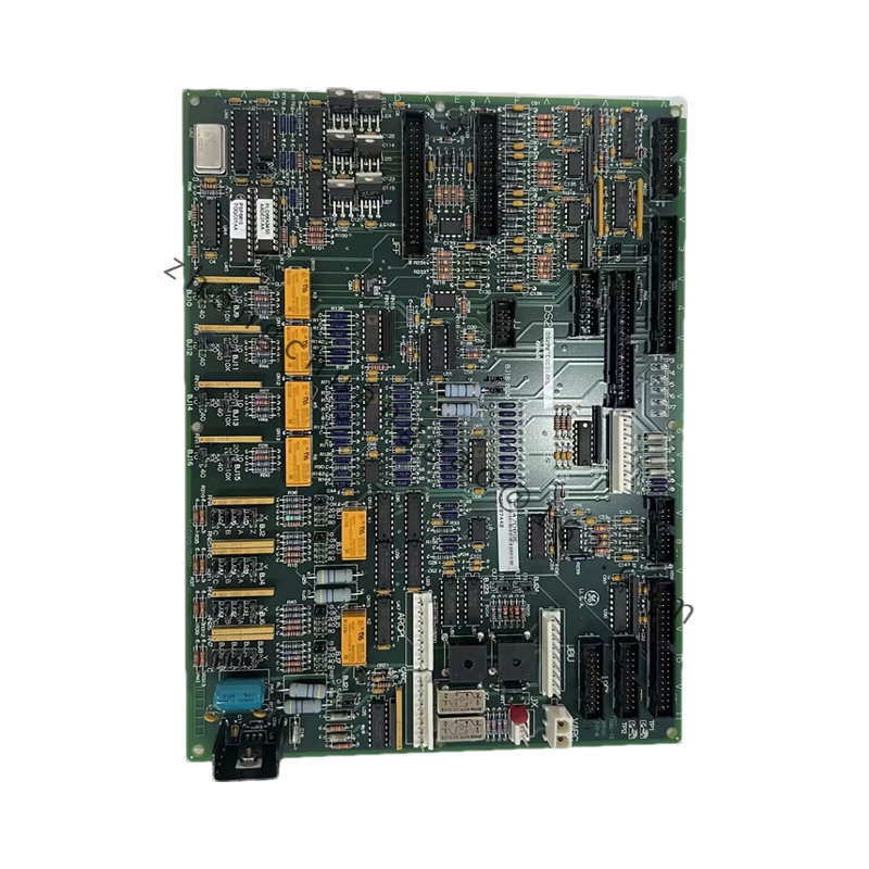
Modular internal design separating power components from control circuitry
Top ventilation holes, bottom air intake
Working Principle: AC input passes through EMI filtering, rectification, and PFC (power factor correction), then high-frequency DC-DC conversion generates multiple regulated DC outputs.
Installation Requirements: Mount in the Mark VI control cabinet using DIN rail or screw fixing. Provide both 120 V and 240 V AC feed for full 1+1 redundancy. Ensure adequate rear clearance for DC output terminal access and top/bottom airflow.
Usage Precautions: Both AC input feeds must be present for true redundancy. Keep ventilation paths unobstructed. The front-panel test button forces a simulated fault—use only during planned maintenance. Observe lockout/tagout procedures before servicing.