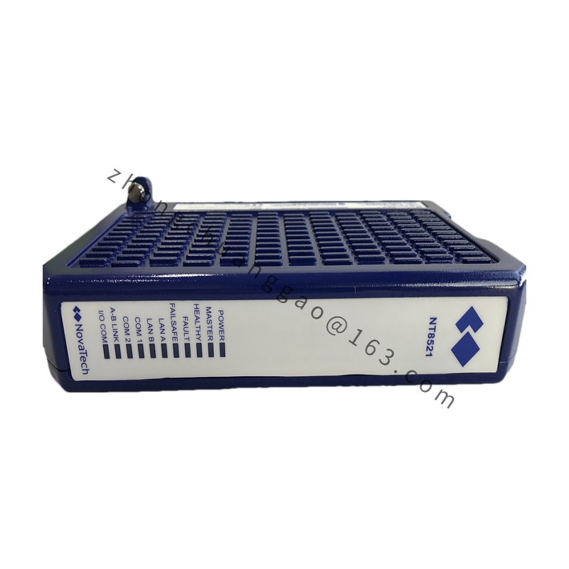
GE IS200TVBAH2A
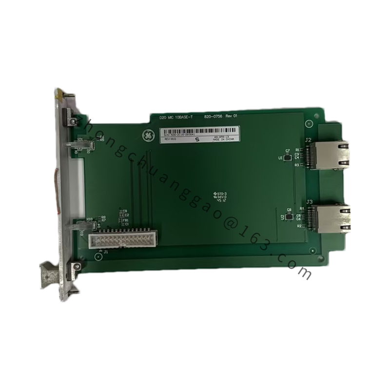
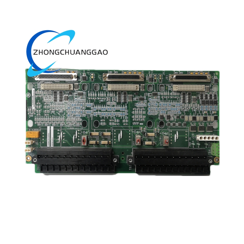
Product Name: Vibration Terminal Board (TVBA)
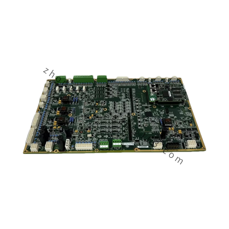
Product Introduction: The IS200TVBAH2A is a vibration terminal board developed by GE (originally GE Fanuc / GE Industrial Systems) for the Mark VI and Mark VIe turbine control platform. It serves as the dedicated interface between field-mounted vibration and position sensors and the control system I/O packs, playing a critical role in the condition monitoring and protection layer for large rotating equipment.
Detailed content
Technical Specifications & Performance Parameters:
- Product Family: GE Mark VI / Mark VIe Turbine Control System
- Module Type: TVBA (Vibration Terminal Board)
- Input Channels: Up to 14 sensor input channels (typical configuration)
- Input Signals: Proximity probes, accelerometers, velocity sensors (Velomitors), seismic sensors
- Output Signals: Conditioned analog vibration signals, position signals, and dynamic pressure signals routed to I/O processor modules (PVIB / YVIB)
- Signal Conditioning: Sensor excitation, transient suppression, open-circuit detection, signal buffering
- Excitation Power: +28 VDC system supply with onboard regulation for sensor excitation
- Isolation: Channel-to-channel and channel-to-ground isolation
- Connectors: 24-point terminal blocks plus high-density system connectors (two 37-pin D-type connectors in typical H2ACC configuration)
- Mounting: Rack-mounted terminal board within Mark VI cabinet system (“Modulator Plate” footprint)
- Dimensions: Approximately 300 × 200 × 100 mm
- Weight: 1.5 – 2.0 kg
- Operating Temperature: –30 °C to +70 °C
- Storage Temperature: –40 °C to +85 °C
- Relative Humidity: 5% to 95% non-condensing
- Diagnostic Features: Open-circuit detection, sensor fault detection, channel diagnostics, board identification
- Redundancy: Supports simplex and Triple Modular Redundant (TMR) architectures
Functional Characteristics: The board handles high-frequency AC signals and negative voltage excitation (–24 VDC) required by industrial vibration probes. It distributes vibration signals to redundant I/O packs (R, S, and T cores) for voted protection logic. The “CC” suffix indicates conformal coating for protection against moisture, dust, and corrosive industrial atmospheres.
Application Scenarios: Gas turbine control, steam turbine control, generator condition monitoring, bearing vibration protection, shaft position sensing, centrifugal compressor protection, and condition monitoring systems for high-speed rotating machinery.
Working Principle: Raw signals from vibration-related sensors are collected at the terminal blocks, conditioned through passive filtering and surge protection circuitry, excited by integrated power circuits, and then transmitted via D-type connectors to downstream PVIB/YVIB I/O packs where all signal processing is performed.
Installation Requirements:
- Install the board onto the designated VME rack or baseplate within the control cabinet, ensuring secure fastening to prevent signal noise from vibration.
- Connect proximity probes or accelerometers to the terminal blocks, ensuring shield wires are correctly terminated to the ground bar to minimize EMI.
- Align and seat the PVIB I/O pack carefully with the D-type connectors and tighten mounting screws.
- Configure sensor sensitivity (e.g., 200 mV/mil) within ToolboxST software for accurate displacement or velocity readings.
Usage Notes:
- The board only handles signal acquisition and conditioning; all processing is done in downstream Mark VI I/O modules.
- This is a legacy / obsolete product, typically sourced via surplus or refurbished industrial automation markets.
- A short circuit on a vibration probe cable is protected by current-limiting resistors and individual channel protection, preventing a single fault from compromising power to remaining sensors.