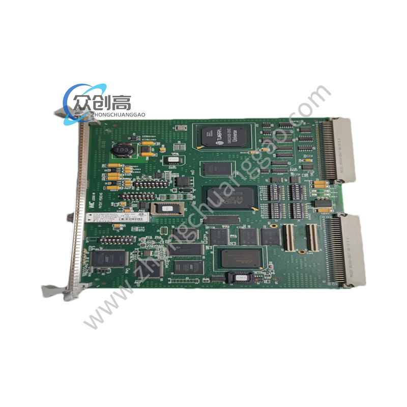
GE IS200TTURH1B
Product Name: GE Mark VI Turbine Protection Input Terminal Board
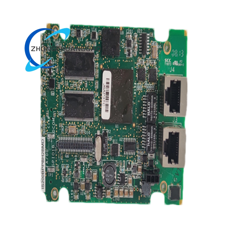
Product Introduction: The IS200TTURH1B is a Primary Turbine Protection Input terminal board developed by GE for Mark VI turbine control systems, used for overspeed protection, synchronization, and breaker permissive control. The board interfaces magnetic pickup speed sensors, shaft voltage monitoring circuits, generator synchronization signals, and breaker permissive logic within turbine protection architectures.
Detailed content
Technical Specifications:
- Series: Speedtronic Mark VI
- Inputs: 12 passive pulse-rate inputs
- MPU Pulse Rate Range: 2 Hz to 20 kHz
- MPU Accuracy: 0.05% of reading
- MPU Sensitivity: 27 mV peak
- Breaker Coil Output: 5 A at 125 V DC
- Shaft Voltage Signal: ±5 V DC pulse monitoring
- Shaft Voltage Wiring Distance: Up to 300 m
- Relay Configuration: K25, K25P, K25A permissive relays
- Supported Architectures: Simplex and TMR
- Wiring Capacity: Accepts up to #12 AWG conductors
- Operating Temperature: −30°C to +65°C
Functional Features:
- Twelve passive pulse rate devices sensing a toothed wheel to measure turbine speed
- Receives generator voltage and bus voltage signals from potential transformers
- Provides 125 V DC output to the main breaker coil (52G) for automatic generator synchronization
- Permissive generator synchronizing relays
Structural Features:
- Two I/O terminal blocks TB1 and TB2 (each held together with two screws and has 24 terminals)
- Shield termination strip to the left of each terminal block connected to chassis ground
- Jumpers JP1 and JP2 to select SMX or TMR for relay drivers K25 and K25P
- TB3 for optional TTL active speed pick-ups
- Connectors: JR5, JR1, JS5, JT5, JS1, JT1
Working Principle: In simplex applications, up to four pulse rate signals can be used to measure turbine speed. In TMR applications, all inputs fan to the three control racks. Control signals from R, S, and T are voted before they activate permissive relays K25 and K25P in TTUR. The VPRO and TREG boards control relay K25A. TTUR receives generator and bus voltages for automatic synchronization with VTUR, the turbine controller, and the excitation system.
Installation Requirements:
- Pre-Installation: Notify operations and place the turbine in a verified shutdown state. Lock out and tag out all control cabinet and breaker power sources. Wait at least 5 minutes for capacitor discharge and verify absence of voltage with a meter.
- Tools Required: Grounded ESD wrist strap, PH1 screwdriver, Fluke 115 multimeter, wire labels, smartphone for documentation photos, flashlight for terminal inspection.
- Data Backup: Export current Mark VI configuration files. Photograph terminal wiring, jumper positions, connector routing, and shield grounding layout.
- Removal: Remove cabinet access covers carefully, label all field wiring and signal connectors, disconnect MPU/shaft voltage/relay wiring evenly.
Usage Notes:
- The TTUR board interfaces directly with turbine protection signals and breaker permissives. Treat every connected circuit like it matters to machine protection.
- A noisy MPU input, failed relay, or grounding issue on this board can create nuisance overspeed trips or failed synchronization attempts.
- Engineers have spent six hours troubleshooting a false overspeed alarm that turned out to be one swapped MPU cable during reinstallation.