Digital guide

You are here:

GE IS200TGENH1A

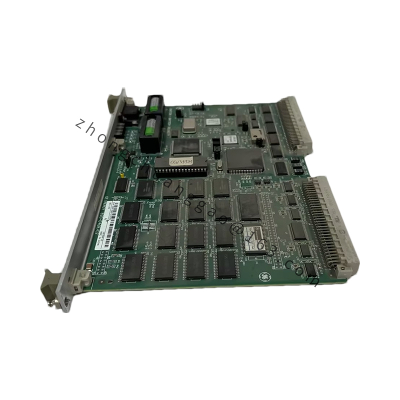
Product Name:​ Generator Monitor (TGEN) Terminal Board
Overview:​ The IS200TGENH1A is a terminal board developed by GE under the Mark VI series. It communicates with the VGEN processor to monitor the three-phase voltage and currents of the generator, as well as to calculate the three-phase power and power factor. It collaborates with the VGEN processor and supports simplex and TMR applications.

Detailed content

Technical Specifications:
  • Manufacturer: General Electric
  • Series: GE Mark VI
  • Function: Terminal Board Generator Monitor
  • Generator and Bus Voltages: 115 V RMS nominal
  • Nominal Frequency: 50/60 Hz
  • Input Loading: Less than 3 VA per circuit
  • Magnetic Isolation: Up to 1,500 V RMS
  • Generator Current Inputs: Normal range 0 to 5 A, over-range up to 10 A
  • Frequency Range of Interest: 45 to 66 Hz
  • CT Inputs: Three single-phase CT inputs, magnetically isolated
  • CT Terminations: Non-pluggable terminal blocks with captive lugs accepting wires up to #10 AWG
  • Analog Inputs: Four inputs, configurable for 4-20 mA or 5, 10, 20 V DC via jumpers
  • Physical Dimensions: 15.00 × 9.00 × 3.00 inches
  • Weight: 4.00 lbs
Functional Features:
  • Monitors two 3-phase generator and bus PTs, three 1-phase generator CTs, and four analog inputs
  • VGEN converts signals and calculates power, power factor, and frequency
  • Test points provided for all PT and CT inputs to verify phase in the field
  • A +24 V DC source is available for all four analog input circuits, each with its own current limit
  • Diagnostics check input signals for high/low hardware limits and high/low system software limits
  • Voltage inputs have open wire detection; relay drivers and coil currents are monitored
  • ID devices on connectors JR1, JS1, and JT1 contain serial number, board type, revision number, and plug location
Configuration:​ Jumpers J1A–J4A select either current or voltage input on analog inputs 1–4.
Working Principle:​ TGEN’s PT and CT inputs are monitored by VGEN, which converts signals and calculates power, power factor, and frequency. In simplex systems a single cable links one TGEN to VGEN; in TMR systems, TGEN connects to three VGEN boards through three distinct wires.
Application Scenarios:​ Gas turbine Speedtronic control systems; generator monitoring and control in power generation facilities.
Installation Requirements:
  • Terminal block 1 is wired with analog current and PT inputs
  • CT is connected to special non-removable terminal blocks TB2, TB3, and TB4 (this safeguards against an open CT circuit)
  • Jumpers J1A and J1B set the desired input current or voltage on analog inputs 1–4
Usage Notes:
  • The software limit check can be changed in the field
  • Observe proper wiring to avoid open CT circuits — use only the dedicated non-pluggable terminal blocks for CT connections

You may also like