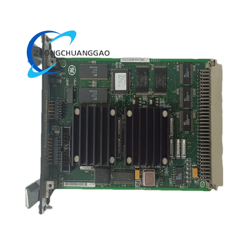
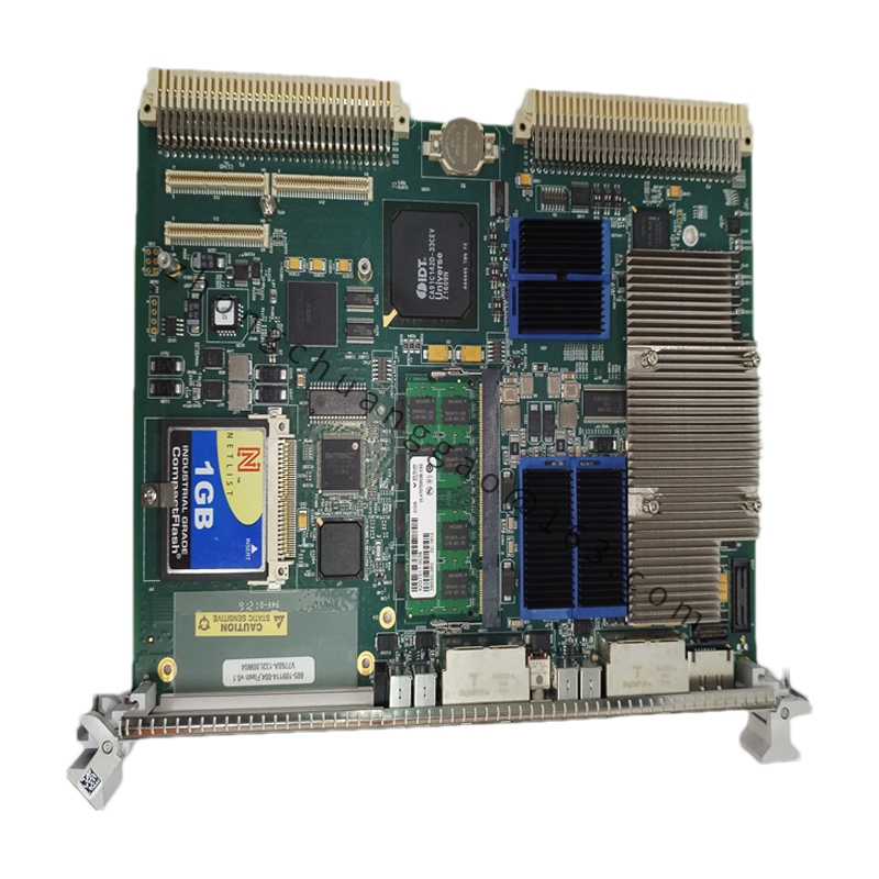
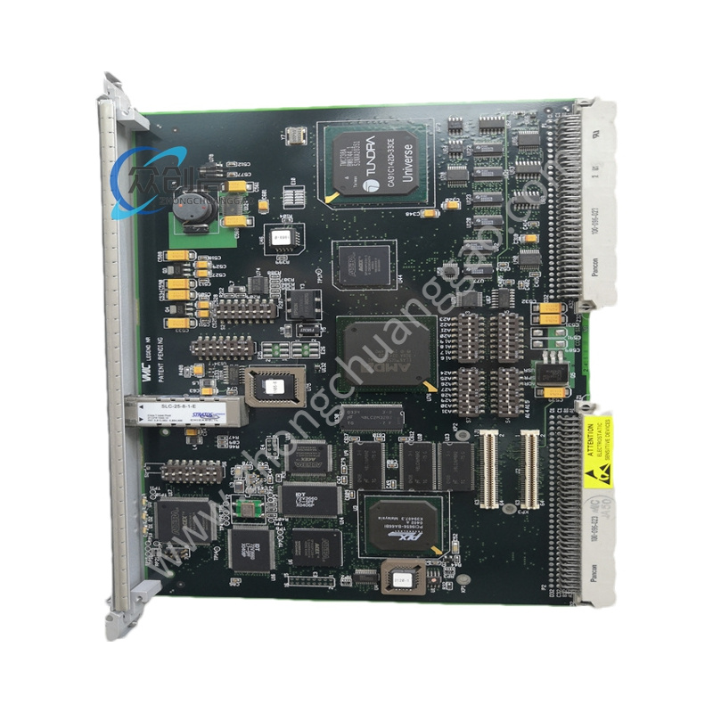
Product Name: GE IS200EDISG1A – EX2100e/Mark VIe Exciter Digital Input/Output Terminal Board
Introduction: A digital I/O terminal board that serves as the dedicated hardware interface for digital input/output signal termination within GE’s EX2100e and Mark VIe exciter control platforms. It links discrete field circuits directly to the processing backbone and processes safety-critical shutdown triggers.
Model: IS200EDISG1A (also cataloged as IS200EDIS Exciter Digital Input/Output Terminal Board)
Digital Inputs: 16 channels
Digital Outputs: 16 channels
Input Type: Dry-contact inputs, 24 V DC logic
Output Type: Relay / solenoid drivers (24–125 V DC)
Response Latency: < 1 ms for trip signals
Isolation: Galvanic isolation, channel-to-system and channel-to-channel
Backplane Power: 28 V DC nominal
Terminal Blocks: Accept wiring up to 2.5 mm² (14 AWG)
Operating Temperature: –40 °C to +70 °C
Dimensions: Approx. 28–30 cm width
Shipping Weight: 4.00 kg
Key Features:
High-speed response (< 1 ms) for critical trip signal transmission
16 digital inputs + 16 digital outputs in a single board
Channel-to-system and channel-to-channel galvanic isolation for high-voltage transient immunity
Directly interfaces discrete field circuits to the EX2100e/Mark VIe processing backbone
Materials & Construction: Terminal board with DIN-rail or rack mounting; industrial terminal blocks rated for 2.5 mm² (14 AWG); chassis ground terminal for low-impedance connection to the protective earth busbar; designated shield-drain grounding bracket.
Working Principle: Discrete field signals (dry contacts) arrive at the terminal blocks, are conditioned and isolated, then transferred over the backplane bus to the exciter control processor. Output channels drive relays/solenoids (24–125 V DC) for trip, de-excitation, and lockout actions. The architecture ensures that safety-critical shutdown triggers are processed with minimal latency.
Application Scenarios: Exciter control and protection in gas turbine-generator units, steam turbine-generator units, and hydroelectric power plants.
Installation & Usage Notes:
Secure the assembly onto the cabinet DIN-rail or rack matrix. Establish a metal-to-metal low-impedance chassis ground connection directly to the master protective earth busbar.
Route low-voltage 24 V DC discrete input logic lines through separate physical wiring conduits, isolated from high-voltage 125 V DC solenoid output driver cables, to suppress capacitive cross-talk.
Land external shield drain wires exclusively at the designated grounding bracket on the terminal board frame. Do NOT ground both ends of the cable shield to avoid ground loops.
Use wire sizing up to 2.5 mm² (14 AWG) for robust physical connectivity.