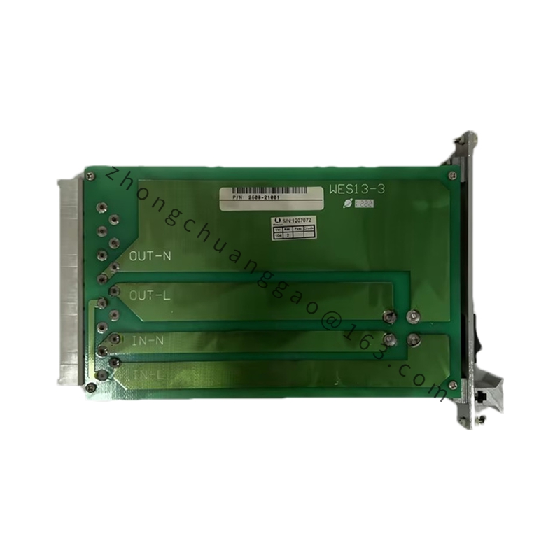
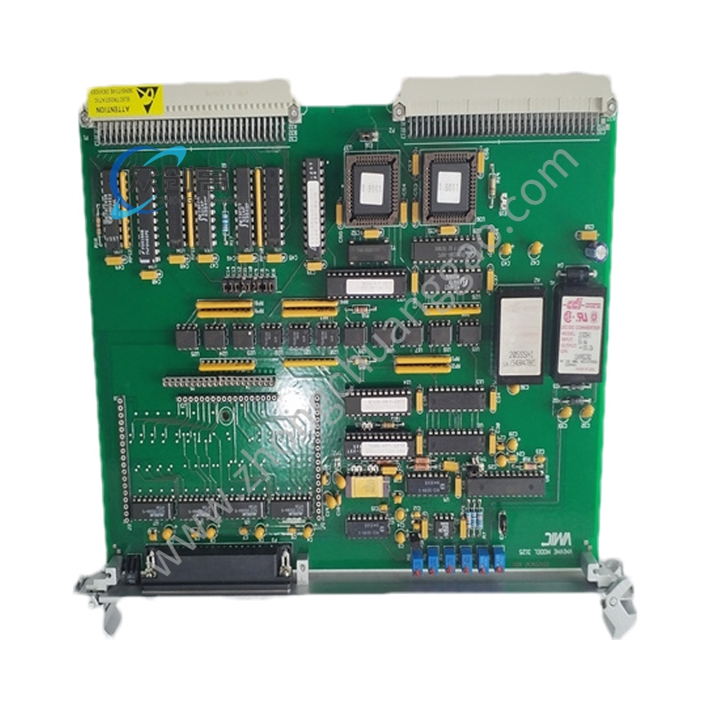
GE IS200BPIBG1AEB
Product Name: Bridge Personality Interface Board (BPIB)
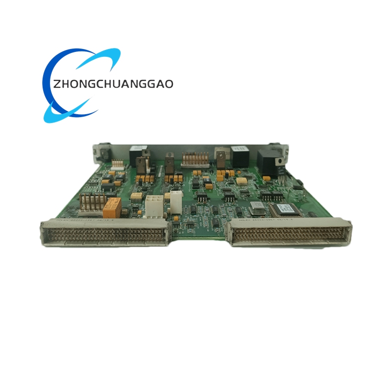
Product Introduction: The IS200BPIBG1AEB is a Bridge Personality Interface Board (functional acronym BPIB) developed by General Electric for the Mark VI series. It serves as the bridge between the gate driver boards and the associated processing units, providing isolated logic-level signal translation, fault capture, and per-phase/per-gate fault control for IGBT drive circuits.
Detailed content
Technical Specifications:
-
Manufacturer: General Electric
-
Catalog: Mark VI
-
Functional Acronym: BPIB
-
Power Input: 17.7 VAC and 5 VDC
-
DC Link Voltage Feedback VCO Range: 0–20 MHz
-
IGBT Driver, ISOLATED 5 VDC: MAX 500 mA
-
Operating Temperature: 0°C to 60°C
-
Storage Temperature: -40°C to 85°C
-
Humidity: 5% to 95%
-
Dimensions: 40 cm × 20 cm × 5 cm
-
Weight: 1.2 kg
Functional Features:
-
Captures faults detected by gate driver boards and reports them to the associated processing units
-
Per-phase and per-gate fault control with per-gate latch
-
Latched driver faults are reported on the phase P fault line whose adjacent IGBT is commanded ON
-
Isolated 5 VDC supply for logic signals to/from the connected gate drive board, derived from the 17.7 VAC feed for improved noise immunity
Material Composition:
-
PCB: Industrial-grade multi-layer board
-
Isolated power stage: Derived 5 VDC isolated converter
-
Connectors: Six plug connectors for IGBT boards; five stab-on connectors for phase A, phase B, phase C, DC link positive, and DC link negative sensing
Structural Characteristics:
-
VME-type rack mount form factor
-
P1 connector on the back edge for rack insertion
-
Narrow front faceplate with retaining clips for board fixation in the VME rack
Working Principle: The 17.7 VAC input is transformed and isolated to generate a 5 VDC isolated supply that powers the gate driver logic. The board continuously monitors gate driver fault lines. When a fault is captured, the corresponding per-gate latch is set and the fault information is forwarded to the associated processing unit over the backplane. The DC link voltage is fed back via a VCO operating across 0–20 MHz. The five stab-on connectors sense phase A, phase B, phase C, and DC link positive/negative potentials for real-time voltage monitoring.
Installation Requirements:
-
Insert the board into the VME rack via the P1 back-edge connector
-
Secure the narrow front faceplate using the retaining clips
-
Connect the six plug connectors to the respective IGBT driver boards
-
Attach the five stab-on connectors to the phase A, B, C and DC link positive/negative sensing points
-
Verify the 17.7 VAC and 5 VDC supplies are present before energizing the IGBT stages
Usage Precautions:
-
Ensure the isolated 5 VDC output does not exceed 500 mA per IGBT driver
-
Confirm DC link voltage is discharged before handling stab-on connections
-
Maintain operating temperature within 0–60°C to avoid VCO drift and latch malfunction
-
Verify the 5% to 95% humidity range is not exceeded with condensation present