Product Name: GE Source-Bridge Interface Board (Mark VI)
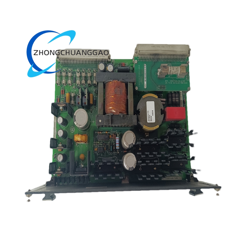
Product Overview: The IS200BICLH1B is a Source-Bridge Interface (BICL) board for GE Mark VI turbine control systems. It integrates 24–115 V AC/DC voltage detection, relay interlock, and a 1024-bit serial EEPROM. It converts field 4–10 mA load signals into high-speed, low-impedance digital values delivered to the controller backplane, ensuring reliable firing and turn-off of high-power IGBT/SCR bridges even in strong EMI environments.
Mounting: Mark VI rack — Slot 5 ONLY, secured with front-panel M3 screws
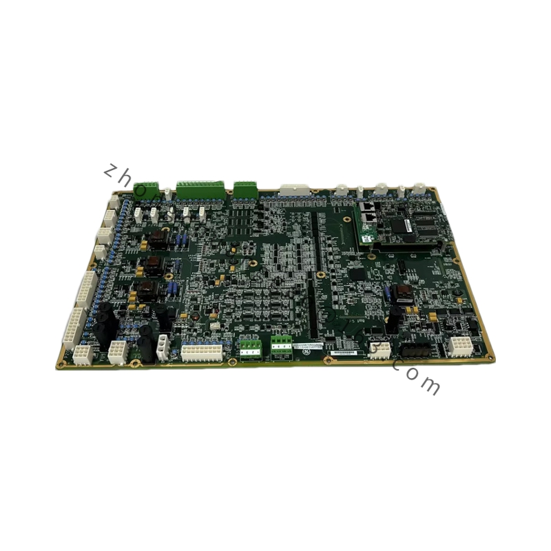
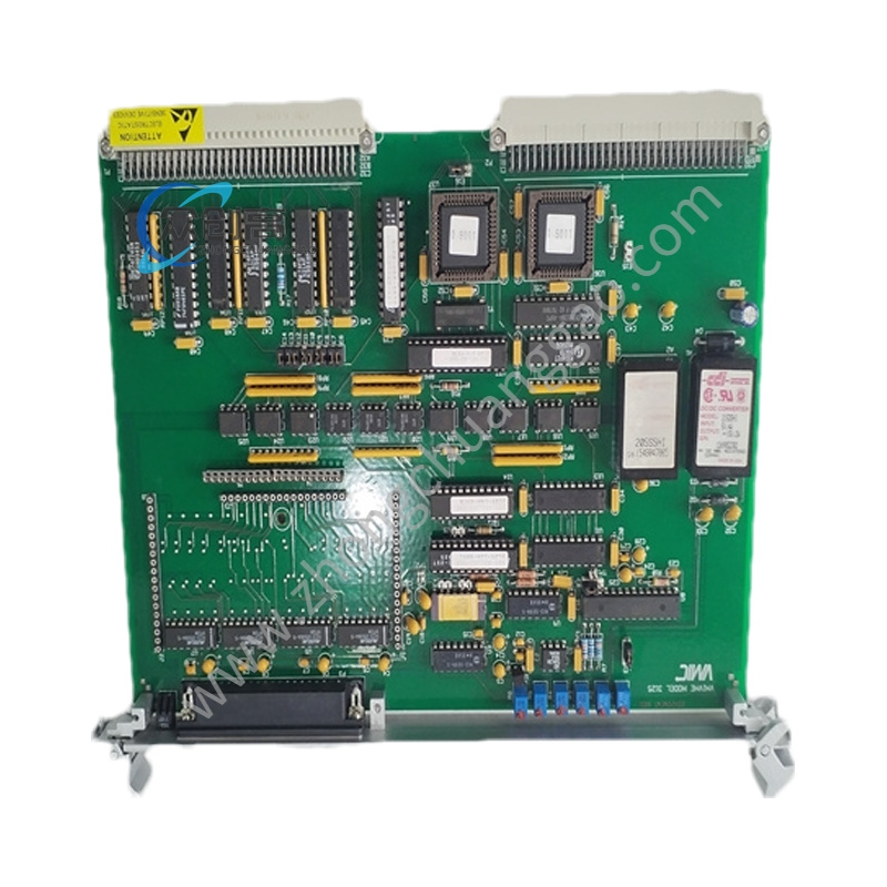
Structural Features: Narrow black front panel with “Install in Slot 5 ONLY” warning engraved. On-board: 4 power relays, 1 MA voltage-detection input terminal, 1 × 1024-bit serial memory chip. No LEDs, no fuses, no user-adjustable hardware (reducing mis-operation risk). Two 96-pin backplane connectors for high-speed data exchange with the Mark VI rack.
Functional Features: Slot-5 dedicated positioning for highest-priority source-bridge signaling; high-reliability relay interlock capable of completing bridge-arm blocking and bypass switching within 300 µs; meets gas-turbine 10% load-step response requirements; compatible with Mark VI and early Mark V upgraded cabinets; supports 16-bit and 32-bit address space.
Working Principle: Field voltage and 4–10 mA current signals are conditioned and galvanically isolated (1500 Vrms), then passed through the onboard relay interlock logic. Upon detecting bridge-arm overcurrent, undervoltage, or gate desaturation, the board drives the 4 relays to block and isolate the bridge within 300 µs, reporting status back to the controller via the dual 96-pin backplane connectors.
Application Scenarios: Source-bridge drive core for power generation, pipeline compression, and LNG liquefaction applications where high-power IGBT/SCR bridges require reliable triggering and fault isolation under severe EMI.
Installation Requirements: MUST be installed in Slot 5 of the Mark VI rack — inserting it into any other slot will cause hardware damage. Secure with M3 front-panel screws. Engage both 96-pin backplane connectors fully. Ensure 24–115 V AC/DC supply is present at the MA terminal.
Usage Notes: Strictly observe the Slot-5-only requirement. The absence of LEDs means fault diagnosis must be done via controller-side software. Keep within 0–60 °C ambient. Observe ESD handling procedures. Verify relay contact ratings (250 VAC / 30 VDC @ 3 A) are not exceeded in the driven circuit.