Digital guide

You are here:

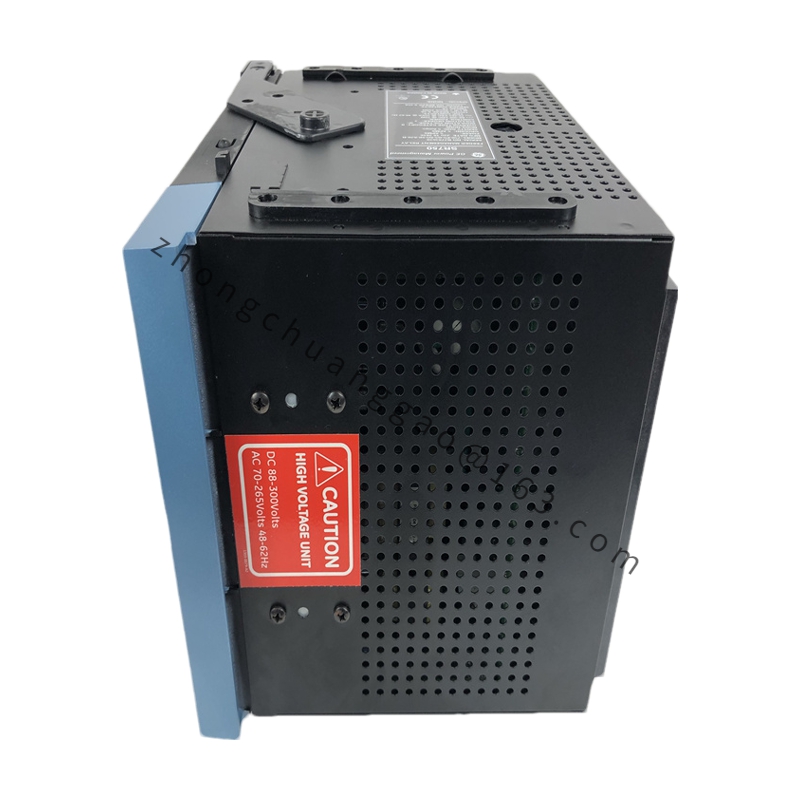
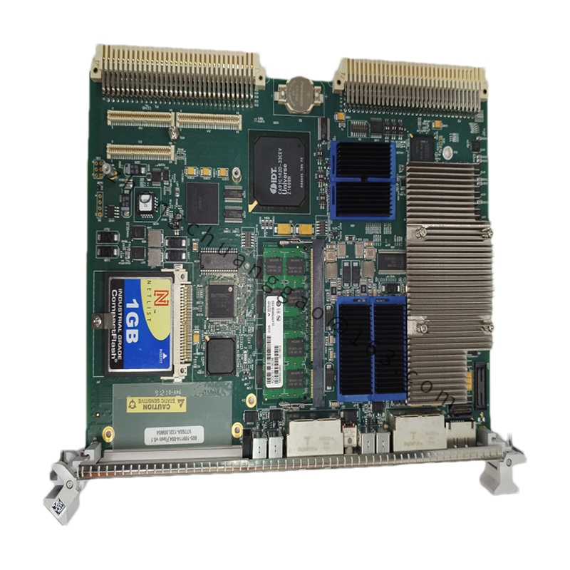
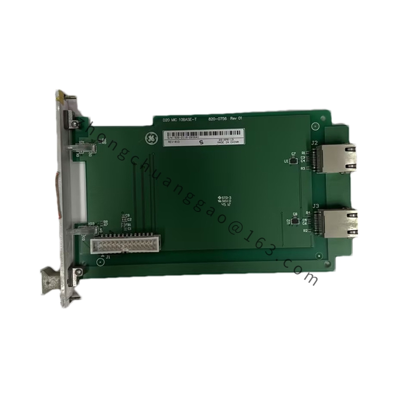
GE DS3820TM2F

Product Name:​ GE Mark VIe Dual-Channel Temperature Monitoring Module
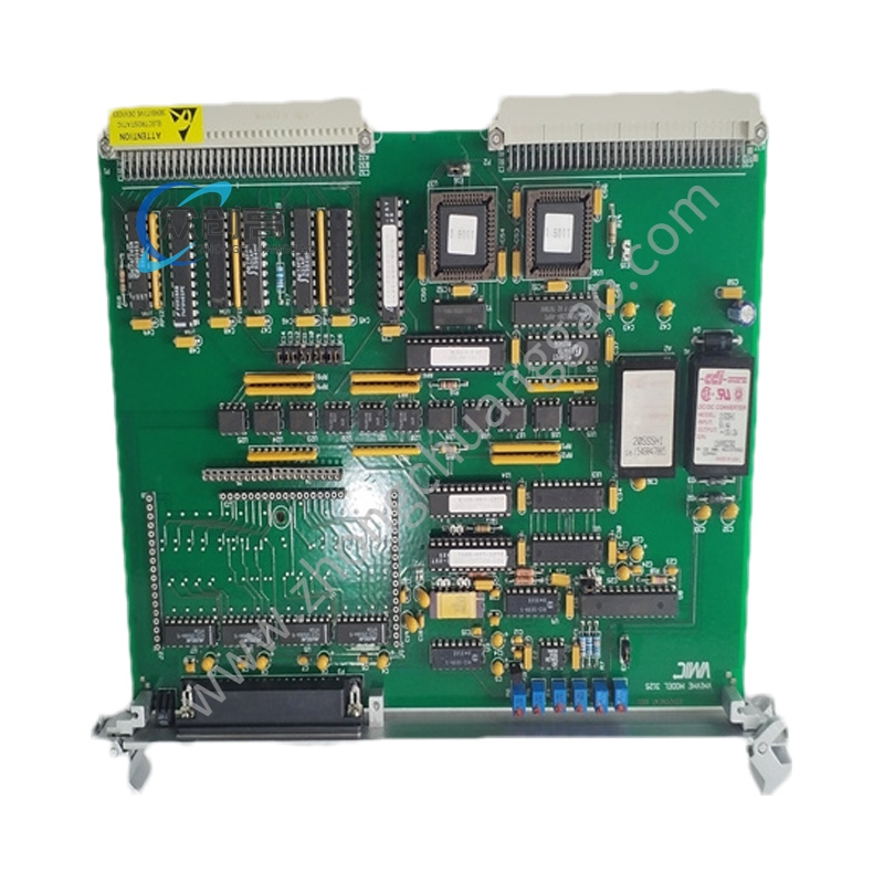
Product Overview:​ The DS3820TM2F is a 2-channel temperature monitoring module within the GE Mark VIe control system, specifically designed to acquire field thermocouple (TC) or RTD signals and convert temperature values into digital signals for upload to the controller.
Detailed content

Technical Specifications:
  • Channels: 2
  • Supported Sensors: K, J, T, E, N, S, R, B type thermocouples / Pt100, Pt1000, Cu50, Cu100 RTDs
  • Measurement Accuracy: ±0.5°C (TC typical) / ±0.3°C (RTD typical)
  • Resolution: 0.1°C
  • Cold Junction Compensation: Built-in, ±1°C accuracy
  • Input Range: TC -200°C to +1800°C (by type); RTD -200°C to +850°C
  • Sampling Rate: 250 ms per channel (typical)
  • Isolation: 500 VDC channel-to-channel, 500 VDC channel-to-backplane
  • Operating Temperature: -20°C to +60°C
  • Power Supply: +5 VDC (backplane)
  • Power Consumption: Approx. 2 W
Functional Features:
  • Automatic sensor type recognition via software configuration, no hardware jumpers required
  • Built-in open circuit detection to distinguish sensor break from out-of-range
  • Linearization processing with direct engineering temperature output
  • Channel fault alarm with real-time status reporting
  • Cold junction compensation self-calibration
Structural & Material Features:
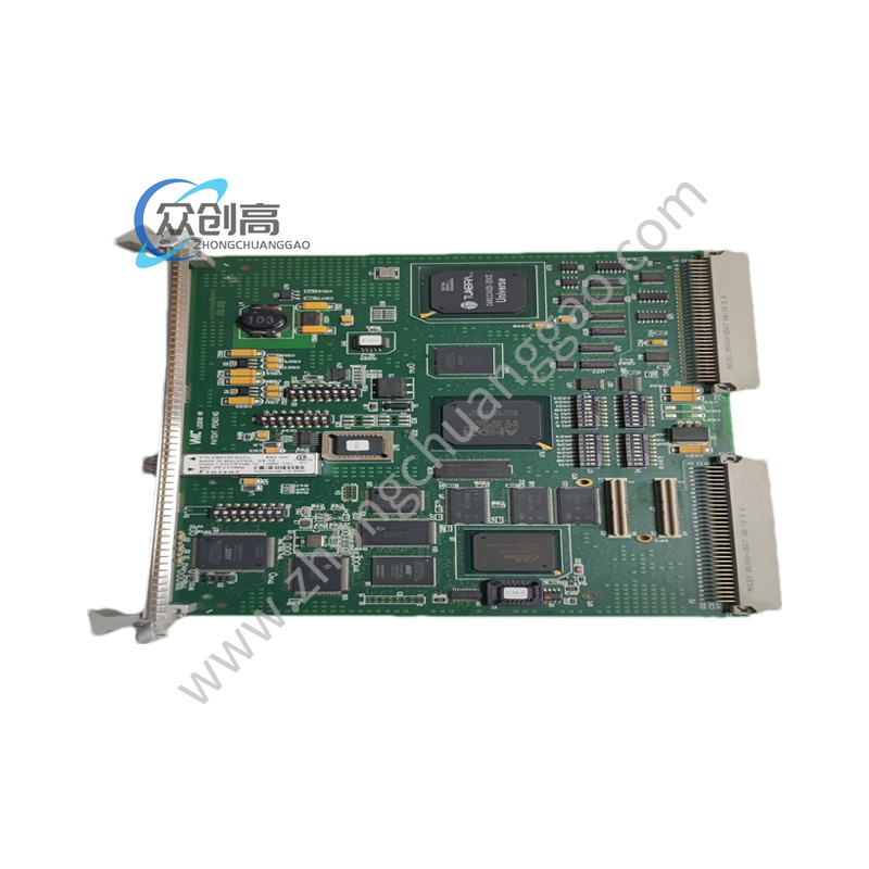
  • VME64 standard PCB (160 mm × 233.4 mm)
  • Front panel: 2 groups of dedicated temperature sensor terminals
  • Top: Run/Fault LED indicators
  • Bottom: DIN 41612 European connector
  • PCB: FR-4 epoxy resin board
  • A/D Converter: 24-bit Sigma-Delta ADC
  • Terminals: Phosphor bronze alloy with gold plating
Application Scenarios:​ Bearing temperature and exhaust temperature monitoring in thermal power plants, turbine temperature in gas turbines, reactor temperature in petrochemical units, and furnace temperature monitoring in metallurgy.
Installation Requirements:
  • Install in Mark VIe VME rack standard slot
  • Thermocouple signal lines must use corresponding calibration extension wire
  • RTD must adopt 3-wire or 4-wire connection to eliminate lead resistance error
  • Sensor cables must be kept away from high-voltage cables, spacing ≥ 300 mm
Usage Notes:
  • Never short thermocouple signals directly, as this causes measurement errors and may damage the module
  • Module address set via DIP switch or software, range 0-15
  • Sensor type change requires reconfiguration in ToolboxST software
  • Regular temperature measurement calibration recommended at least annually

You may also like