Product Name: GE Mark IV Speedtronic Power Supply Control Board (PSCB)
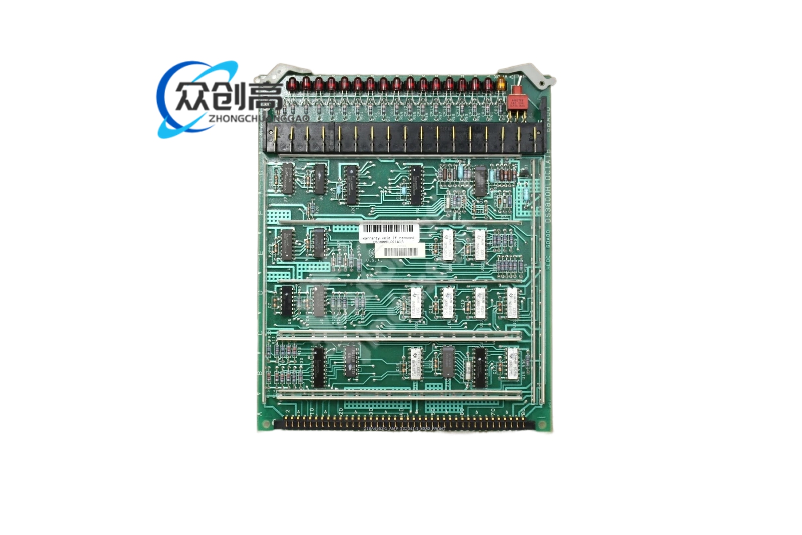
Overview: The DS3820PSCB1C1B is a centralized power supply assembly developed for GE Speedtronic Mark IV gas and steam turbine control cabinets. It converts the plant’s DC control bus into multiple regulated and isolated DC rails that feed CPUs, analog I/O, signal conditioning and relay driver boards. The unit is built for continuous duty in high-vibration turbine enclosures and supports N+1 redundant parallel operation in the rack.
Certifications: CE, UL 508, CSA C22.2 No.14, IEC 61131-2
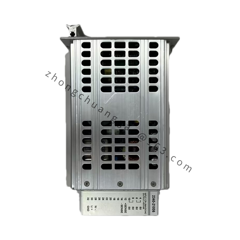
Structural Features: Rugged metal integrated housing with large finned heatsink for power transistor dissipation; multiple high-reliability multi-pin connectors directly mate with the Mark IV backplane; built-in voltage and current sensing circuits report power faults to the main controller; front panel carries PWR OK (green) and FAULT (yellow) status LEDs.
Functional Features: Galvanic isolation between strong and weak circuits suppresses inverter and motor surge interference; short-circuit auto current-limit with latch and auto-recovery after fault clearance; over-voltage/under-voltage protection; input loss detection; internal over-temperature power derating with alarm; all faults generate SOE events stored in the cabinet alarm log.
Application Scenarios: Gas and steam turbine control in power generation plants; compressor and pump drive control in oil & gas; industrial automation requiring clean multi-rail DC distribution to Mark IV racks.
Working Principle: The incoming 80–140 VDC is stepped down and regulated into +5 VDC / +15 VDC / –15 VDC by switching and linear regulator stages. Output current and voltage are sampled in real time; when limits are exceeded the corresponding protection circuit latches the output and raises the FAULT LED while reporting the event to the host controller via the backplane.
Installation Requirements: Mount in the dedicated Mark IV standard rack slot; align the module with the guide rails and press evenly until the backplane connector fully seats; torque the front-panel retaining screws to secure frame grounding; support hot-swap replacement only after the rack power sequence permits — otherwise de-energize first.
Usage Precautions: Verify the incoming DC polarity and voltage range before energizing; ensure cabinet ventilation paths are unobstructed to prevent heat accumulation; never operate with the metal housing cover removed; record all connector positions before removal to avoid mis-mating during reinstallation.