Digital guide

You are here:

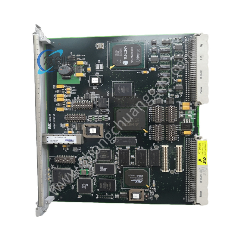
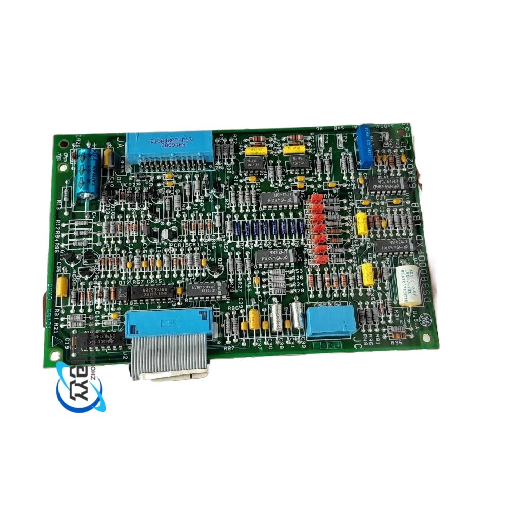
GE DS3820PS1B

Product Name:​ GE Mark VIe Power Supply Module (Basic Type)
Product Overview:​ The DS3820PS1B is the basic power supply module of the GE Mark VIe control system, serving as the general foundation version within the DS3820PS1B series.
Technical Specifications:
  • Input Voltage: 120 VAC / 240 VAC (selectable), 50/60 Hz
Detailed content

  • Input Range: 85 VAC to 264 VAC (full range)
  • Output Voltages: +5 VDC / +24 VDC / +5 VSB (standby)
  • +5 V Output Current: 10 A (max)
  • +24 V Output Current: 5 A (max)
  • Total Output Power: Approx. 170 W
  • Efficiency: ≥ 85%
  • Ripple & Noise: ≤ 50 mVpp (+5 V)
  • Protection: OVP / OCP / SCP / OTP
  • Operating Temperature: 0°C to +55°C
  • Cooling: Natural convection (fanless)
  • Dimensions: VME64 standard size (160 mm × 233.4 mm)
Functional Features:
  • Provides three DC outputs (+5 V, +24 V, +5 VSB) for the Mark VIe rack
  • Supports N+1 redundant configuration with two modules in parallel
  • Complete overvoltage, overcurrent, short circuit, and overtemperature protection
  • Front panel LED indicators for real-time power status display
  • Online replacement supported (when system configuration permits)
Structural & Material Features:
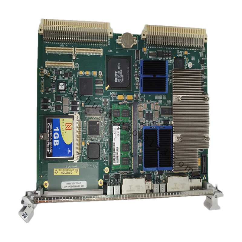
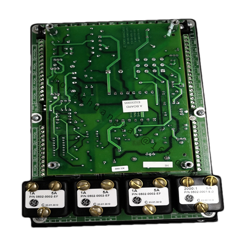
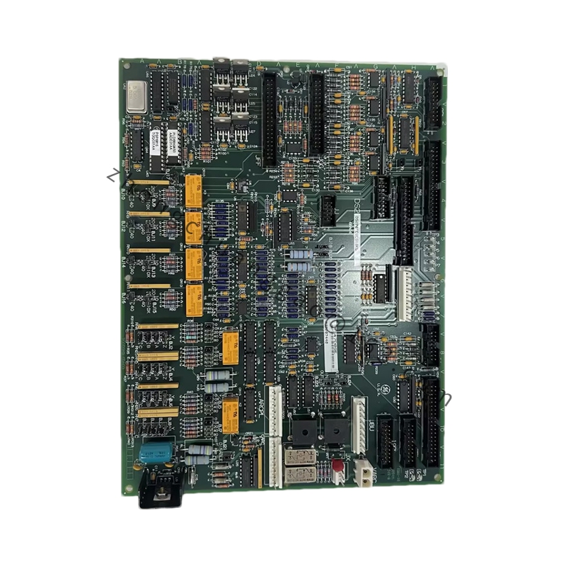
  • VME64 standard PCB card
  • Front panel: AC input terminals, DC output terminals, ground terminal, status LEDs
  • Bottom: DIN 41612 European connector (96-pin)
  • Enclosure: Galvanized steel sheet with anti-corrosion coating
  • PCB: FR-4 epoxy fiberglass board
  • Transformer: Class B insulation (130°C), copper wire winding
  • Connectors: Phosphor bronze contacts with nickel plating
Application Scenarios:​ Thermal power, gas turbine control, petrochemical DCS, water treatment, paper and pulp, metallurgy.
Installation Requirements:
  • Install in Mark VIe rack designated power slot
  • AC input must connect to redundant UPS power supply
  • Redundant operation must use current sharing connection cable
  • Ground resistance ≤ 4 Ω
Usage Notes:
  • Power-on sequence: Connect AC power first, then start the controller
  • Strictly prohibit short circuit or overload at output
  • Module address set via DIP switch (0-15)
  • Regularly check LED status; refer to Mark VIe fault code manual for troubleshooting

You may also like