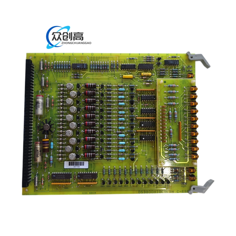
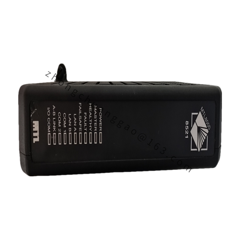
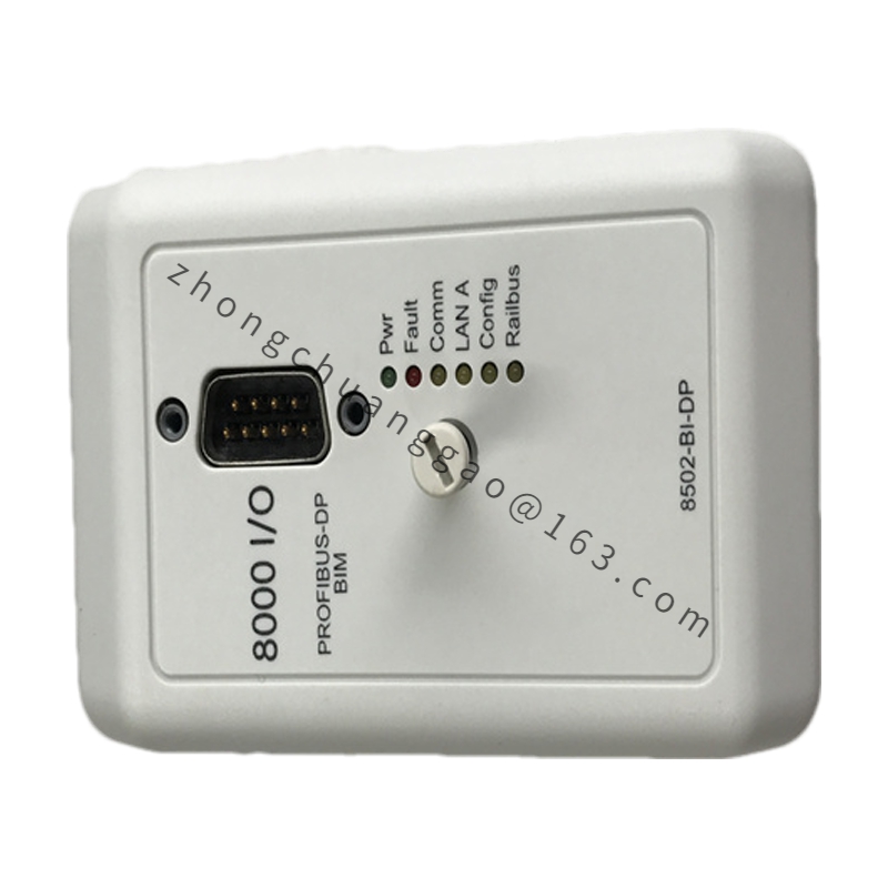
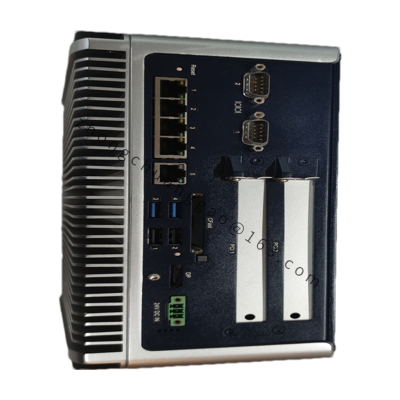
Product Name: Generator Protection Relay / Network Gateway Communication Interface
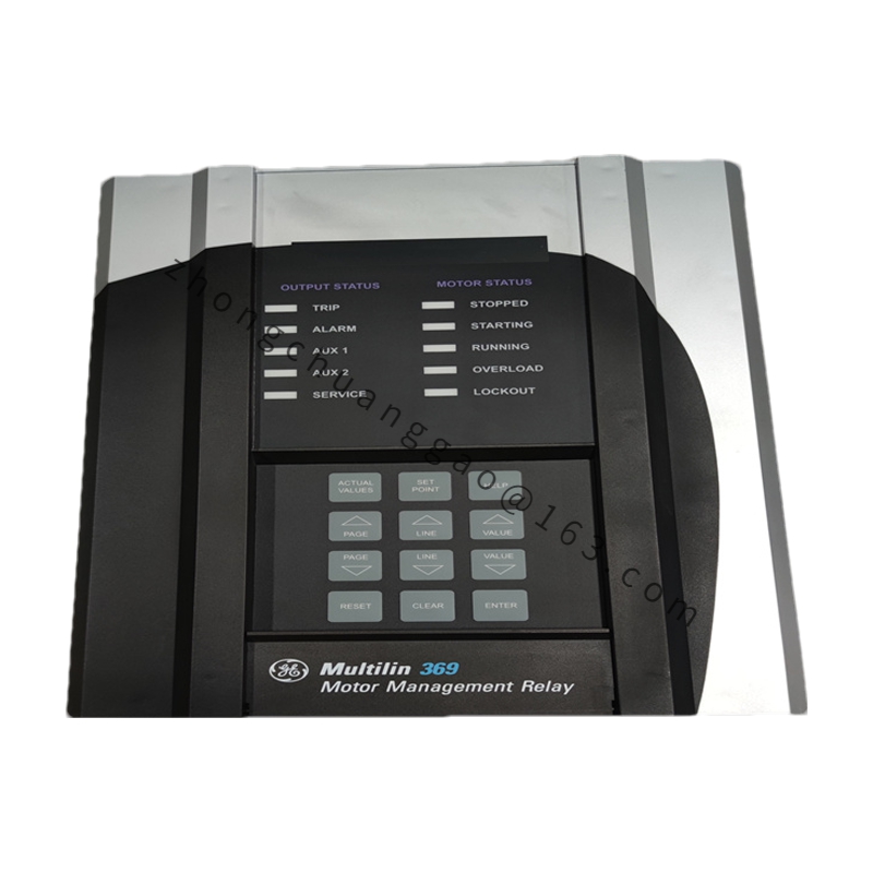
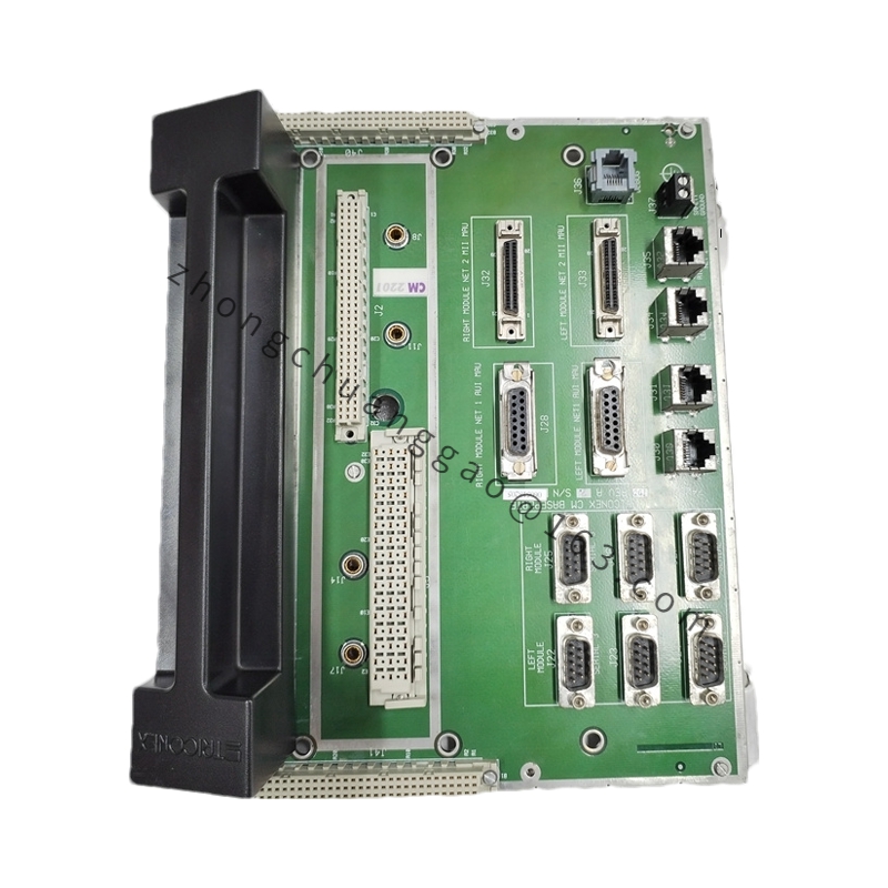
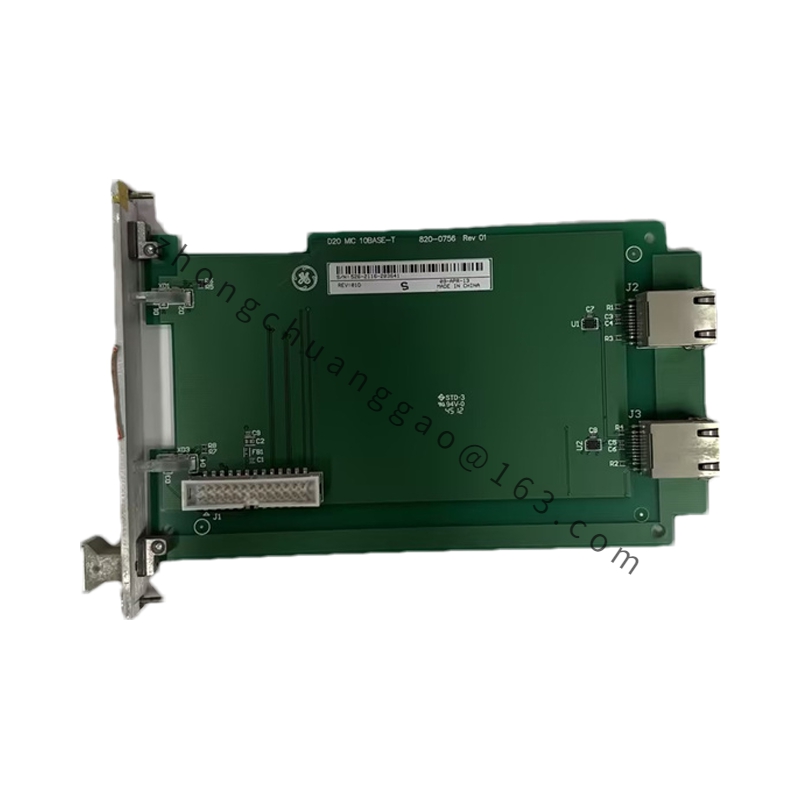
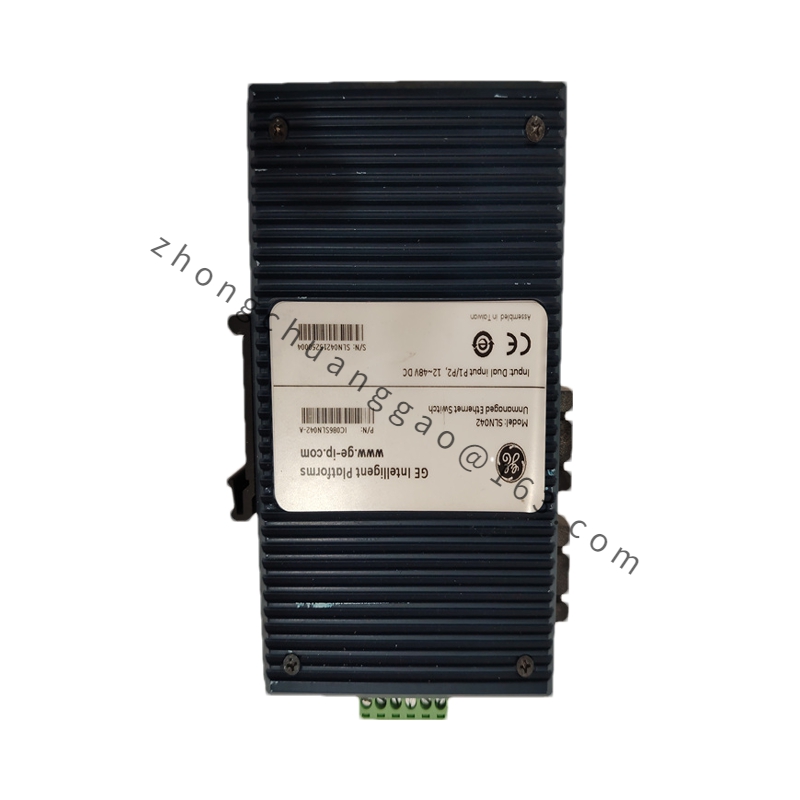
Product Introduction: The GE DS3820NGDB1B is a generator protection and communication device within GE’s Mark IV/V/VI control system family. It integrates more than 12 generator protection functions, replaces multiple traditional protective relays, and acts as a data bridge connecting GE control systems to external enterprise networks or third-party SCADA platforms.
Communication Interfaces: RS-485 Modbus RTU, RS-232, optional fiber optics
Operating Temperature: -20 °C to +70 °C
Protection Rating: IP51 (front panel)
Installation: Panel flush mounting, cutout dimension 138 mm × 138 mm
Key Features: Integrated 12+ generator protection functions; fault waveform recording; Sequence of Events (SOE) recording with 1 ms time resolution; programmable logic for custom protection schemes; LCD display with multilingual menu support; remote communication and SCADA integration.
Application Scenarios: Thermal power plants, hydroelectric plants, gas turbine power plants, and industrial captive power stations.
Structural Features: Square flush-mount design with 138 mm × 138 mm cutout; 4-line × 20-character LCD on front panel; 4 programming keys (up/down/left/right + confirm); bottom terminal block supporting 1.5–4 mm² wire cross-section.
Working Principle: The relay collects generator current and voltage signals via CT (Current Transformer) and PT (Potential Transformer), performs protection algorithm calculations through an internal DSP processor. When any protection condition is met and the delay is reached, it drives the output relay to trip the generator circuit breaker, while recording fault data and uploading it via the communication interface.
Installation Requirements: Panel cutout 138 mm × 138 mm, installation depth ≥ 80 mm; CT secondary must be reliably single-point grounded; communication lines use shielded twisted pair, maximum length 1200 m (RS-485); power input should be connected to UPS or regulated power supply.