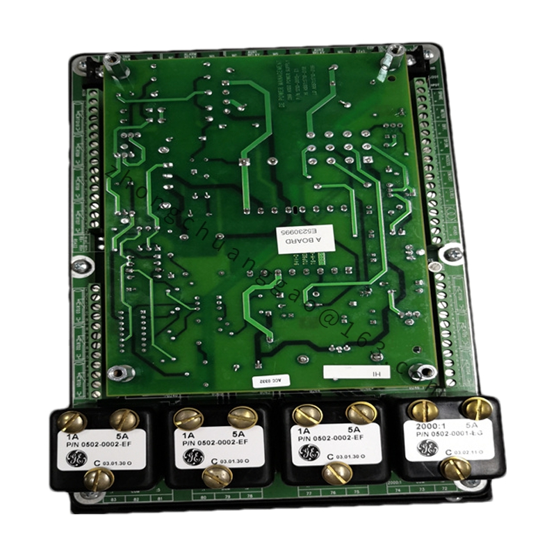
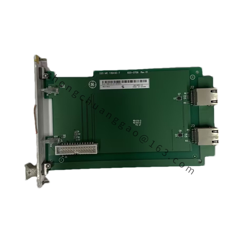
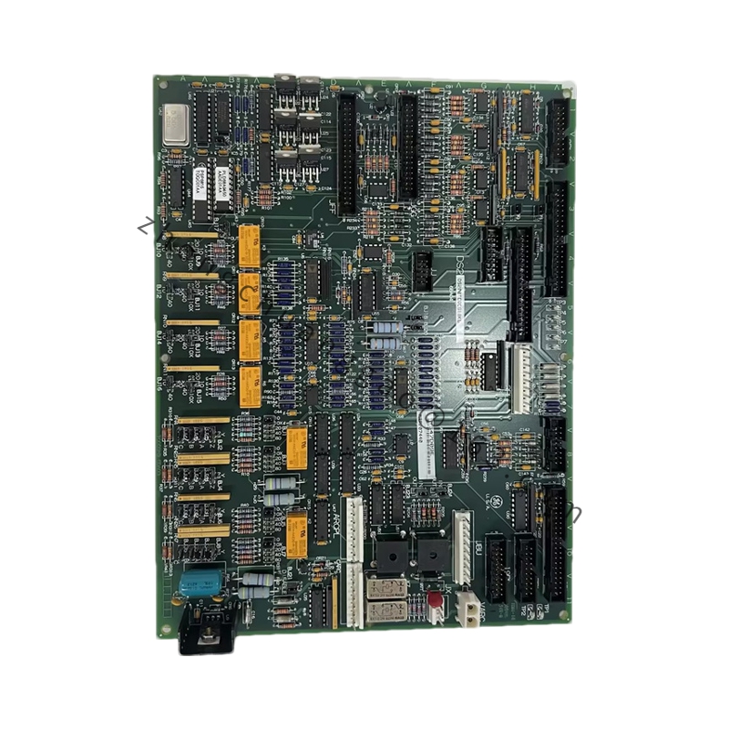
GE DS3815PMMA1F1B
Product Name: GE Mark VIe Pulse Measurement Module (15-Channel)
Product Overview: The DS3815PMMA1F1B is a 15-channel pulse measurement and counting module within the GE Mark VIe system, designed to acquire frequency/pulse signals from field rotating machinery or flow meters and convert them into engineering values such as RPM and accumulated flow for the controller.
Detailed content
Technical Specifications:
- Channels: 15
- Input Signal Type: Frequency (pulse)
- Frequency Measurement Range: 0.1 Hz to 100 kHz (typical)
- Counter: 32-bit
- Resolution: 1 Hz (frequency mode) / 1 pulse (count mode)
- Input Levels: TTL compatible (5 V) or 24 VDC opto-isolated input
- Input Impedance: ≥ 10 kΩ (voltage input) / ≤ 1 kΩ (current input)
- Isolation: Per-channel independent isolation, 500 VDC isolation voltage
- Gate Time: 1 s / 10 s / 100 s (configurable)
- Operating Temperature: -20°C to +60°C
- Power Supply: +5 VDC (backplane)
- Power Consumption: Approx. 3 W
Functional Features:
- Supports four operating modes: frequency measurement, period measurement, pulse counting, and RPM calculation
- Built-in digital filter with configurable anti-jitter time to eliminate signal glitches
- Upper/lower limit alarm triggering
- Wire-break detection with automatic alarm on input signal loss
- Each channel independently configurable for engineering units, range, and alarm thresholds
Structural & Material Features:
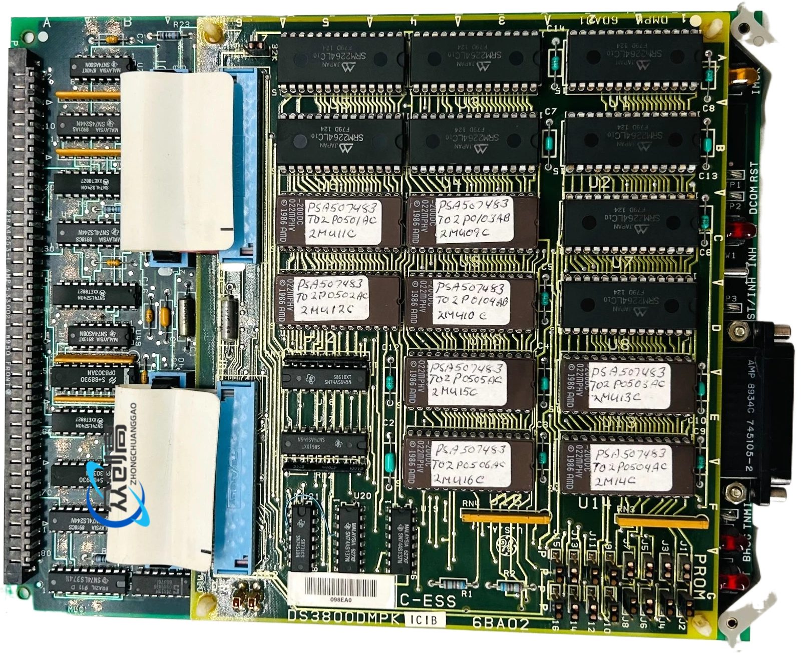
- VME64 standard PCB (160 mm × 233.4 mm)
- Front panel: 15 groups of terminal blocks arranged in groups
- Top: Run/Fault LEDs
- Bottom: DIN 41612 European connector
- PCB: FR-4 epoxy fiberglass board
- Opto-isolators: High-speed photocouplers
- Terminal connectors: Phosphor bronze with tin plating, high-temperature resistant
Application Scenarios: Steam turbine RPM monitoring in thermal power plants, hydro turbine RPM in hydropower plants, flow metering in petrochemical applications, and speed monitoring in wind power generation.
Installation Requirements:
- Install in Mark VIe VME rack standard slot
- Pulse signal lines must use shielded cable with shield single-point grounded at control cabinet side
- Distance between pulse signal source and module should not exceed 100 meters (signal conditioner required for longer distances)
Usage Notes:
- Pulse input signal amplitude must comply with module specifications (5 V TTL or 24 VDC)
- Verify module response capability for high-frequency signals (>50 kHz)
- Module address set via DIP switch, range 0-15
- Cumulative counter automatically overflows to zero at upper limit; handle in program logic