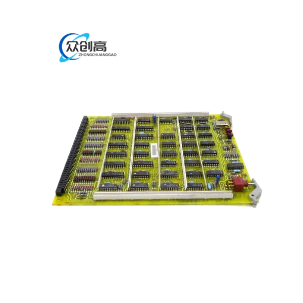
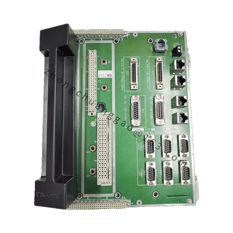
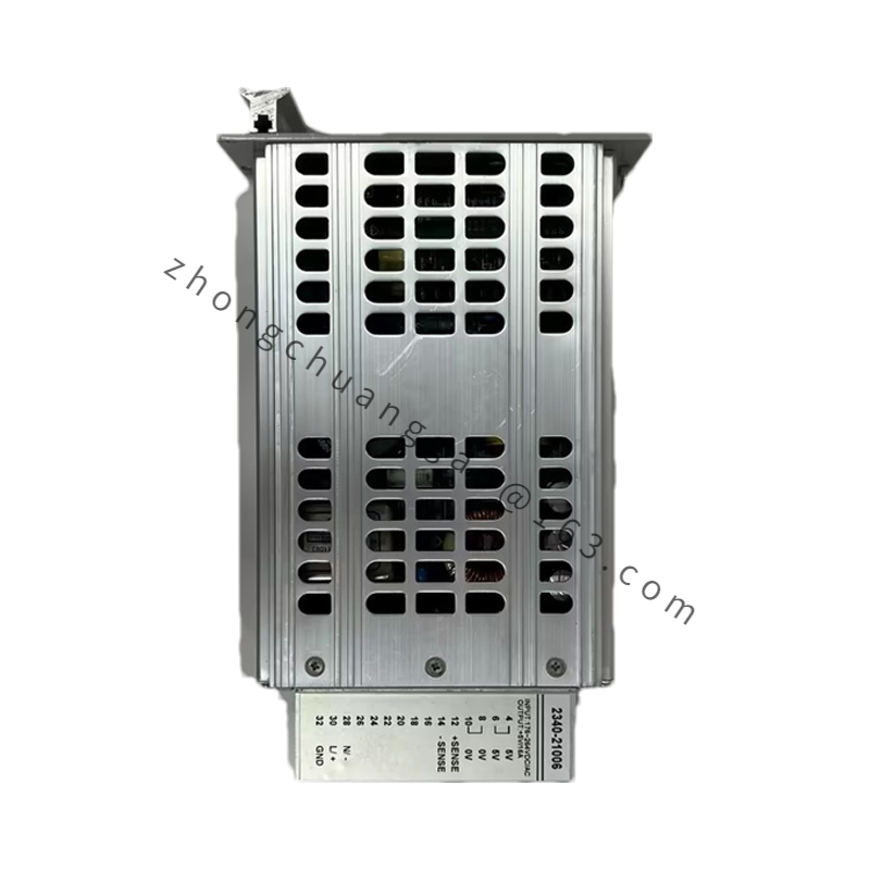
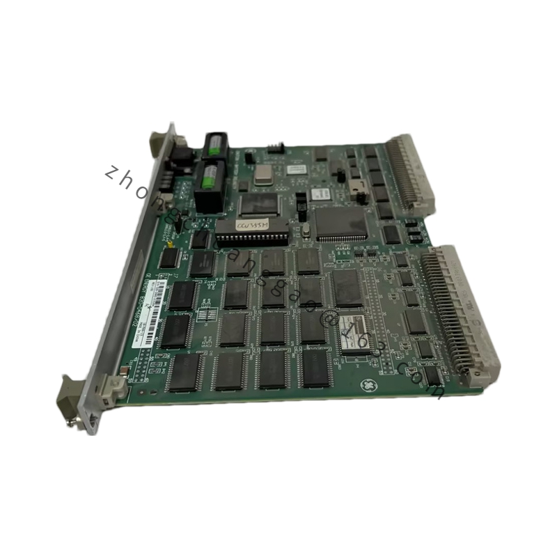
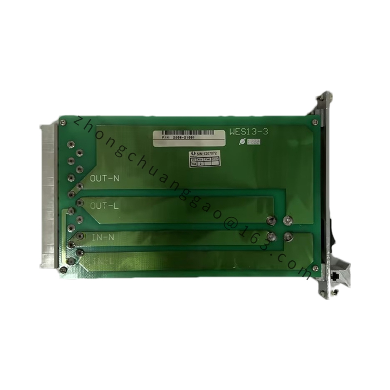
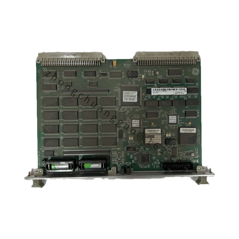
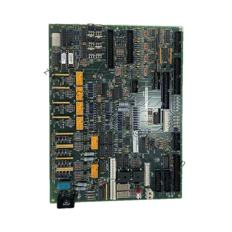
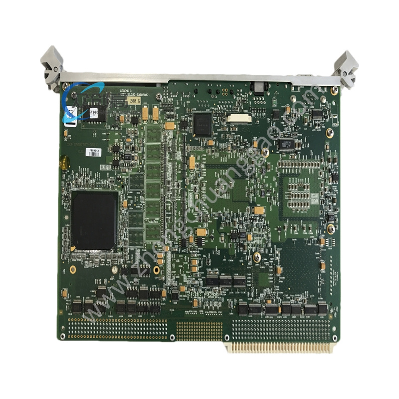
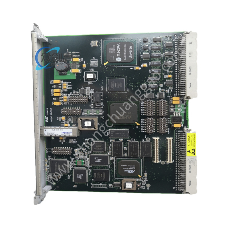
Product Name: GE Speedtronic Mark IV Printed Circuit Board (PCB Control Board)
Product Introduction: The DS3815PLNC1 is an industrial printed circuit control board belonging to GE’s Speedtronic Mark IV family, used in legacy gas and steam turbine management systems. The Mark IV architecture is built on three sets of identical microcomputers that continuously monitor critical turbine controls and parameters; critical outputs such as trip commands are issued only when two or more microcomputers agree, improving reliability and minimizing turbine outage rates.
System Integration: Mark IV backplane architecture
Communication: Backplane communication interface
Operating Temperature: Typically 0°C to 60°C
Storage Temperature: −40°C to +85°C
Board Components: Three test points (TP), one ST point, spare PTH, one amber “IMOK” LED, three resistor networks, thirteen jumper switches (some multi-positional), 42 circuits including triple 3-input NAND gates, hex/quad D-type flip-flops, 8-bit high-speed CMOS Static RAM, 3M 5400 Textool PGA-to-LCC converter, octal buffers/line drivers, and retriggerable monostable multivibrators
Connectors: Two mating connectors — 218A4553-1 Amp 533002-1 and 218A4637-P5 8749 — placed on short board edges
Functional Features: Industrial control signal processing; communicates with other Mark IV PCBs via dedicated backplane connectors; nylon extractor clips on two board corners for safe handling
Application Scenarios: GE legacy turbine control environments, gas and steam turbine management systems
Material Composition: FR-4 printed circuit board substrate; ceramic-covered metal film resistors; industrial-grade electronic components
Structural Features: Drilled at all four corners with nylon extractor clips; DIP-switch and jumper-configurable
Working Principle: Executes control and monitoring logic within the Mark IV triple-redundant turbine protection architecture, exchanging signals with peer boards via backplane connectors
Installation Requirements:
Notify operations of expected downtime and apply lockout/tagout procedures
Remove cabinet power and wait at least 5 minutes for discharge
Wear an ESD wrist strap and work on an ESD mat
Duplicate all jumper and DIP-switch positions exactly from the original board before removal
Align with guide rails and insert evenly until fully seated; do not twist the card
Photograph the original configuration before removal for reference
Usage Notes:
Exact ratings vary by hardware revision and application history
Obsolete model — available only through legacy surplus channels